
User's Manual


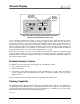
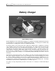
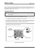
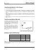

Table Of Contents
- Mark III Directional Drilling Locating System
- Table of Contents
- Table of Contents (Cont.)
- Table of Contents (Cont.)
- Safety Precautions and Warnings
- Safety Precautions and Warnings (Continued)
- Dear Customer:
- 3-3000-00b-F.pdf
- 3-3000-00c-F.pdf
- Receiver
- Display Window Icons
- On/Off
- Receiving the Transmitter’s Signals
- Clicking vs. Holding the Trigger
- Changing the Receiver’s Channel Setting
- Changing the Depth Measurement Units (English vs. Metric)
- Battery Status Display for Receiver and Transmitter
- Warning Tones for Transmitter Overheat
- Ultrasonic Function
- Calibrating the Receiver
- Using Depth Antenna Plumb Line to Mark Locate Points
- Finding Firmware Version
- 5.0 Series Firmware Functions
- Receiver
- 3-3000-00d-F.pdf
- 3-3000-00e-F.pdf
- 3-3000-00f-F.pdf
- 3-3000-00g-F.pdf
- 3-3000-00h-F.pdf
- 3-3000-00i-F.pdf
- 3-3000-00j-F.pdf
- Locating
- Locating Mode
- Locate Points (FNLP & RNLP) and Locate Line (PLL)
- Handling the Receiver
- Distance Between FNLP and RNLP Due to Depth, Pitch, and Topography
- Using Plus/Minus Indicators for Locating
- Locating the Transmitter from the Drill
- Locating the Transmitter from the Front
- Method for Confirming Position
- Locating on the Fly
- Off-Track Locating
- Splitting the Front and Rear Negative Locate Points
- Four-Turn Technique
- Calculating Depth Based on Distance Between FNLP & RNLP
- Running off Pitch or Calculating Depth from Pitch
- Transmitter’s Signal Shape
- Antenna Configuration
- Signal Reception
- Front and Rear Negative Locate Points
- Positive Locate Line Above Transmitter
- Locating
- 3-3000-00k-F.pdf
- 3-3000-00l-F.pdf
- 3-3000-00m-F.pdf
- 3-3000-00n-F.pdf
- 3-3000-00o-F.pdf
- 3-3000-00p-F.pdf
®
Remote Display
Remote Steering
Drill
Drill Path
Transmitter
Under
Roadway
Receiver Placed
on Side (Drill
Path Is Aligned
with Target Point
on Front Panel)
Target Point
Setting up DigiTrak Receiver
for Remote Steering
Remote steering is used to cross streams and
roadways or other inaccessible areas when it is
not possible to walk over the transmitter. To
initiate the remote steering capability, the
receiver is placed in front of the transmitter as
the “target.” The distance the receiver can be
placed ahead is limited by the range of the
transmitter and interference.
With the transmitter powered up and in the
housing ready to drill, walk with the receiver
(powered up and trigger held in) on the surface
over the intended borepath to the “target” loca-
tion. Verify that the receiver displays at least
250 points of signal at target location. Place
the receiver on its side so that the orange arrow
on the receiver points toward the ground. The
target point on the receiver is the center point
between the two depth/locating antenna
screws. The receiver’s front panel should face
the drill. To position the receiver properly, it is
important to pivot the receiver using the center
point between the two antenna screws as the
axis of rotation. When the receiver is properly
pivoted on this axis, the vertical bars (indicating
the transmitter’s position) will line up with the
two triangles (indicating the target) in the center
of the remote steering window. When the
receiver is in its target position, its top surface
must be level. If necessary, place shims under
the receiver to level it.
Axis of
Rotation
Depth/Locating
Antenna Screws
Target Point
Front Panel
Using DigiTrak Receiver for Remote Steering
On the remote steering window, the receiver
(target) is represented by two triangles, one
above and one below the window; the
transmitter is represented by a vertical bar in
this window (see photo on next page). If the bar
is to the right of the triangles, the tool will need
to be steered to the left so that the steering indi-
cator is lined up with the triangles; if the bar is to
the left of the triangles, the tool will need to be
steered to the right.
DigiTrak
®
Mark III Operator’s Manual 27