
User's Manual


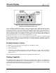
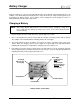

Table Of Contents
- Mark III Directional Drilling Locating System
- Table of Contents
- Table of Contents (Cont.)
- Table of Contents (Cont.)
- Safety Precautions and Warnings
- Safety Precautions and Warnings (Continued)
- Dear Customer:
- 3-3000-00b-F.pdf
- 3-3000-00c-F.pdf
- Receiver
- Display Window Icons
- On/Off
- Receiving the Transmitter’s Signals
- Clicking vs. Holding the Trigger
- Changing the Receiver’s Channel Setting
- Changing the Depth Measurement Units (English vs. Metric)
- Battery Status Display for Receiver and Transmitter
- Warning Tones for Transmitter Overheat
- Ultrasonic Function
- Calibrating the Receiver
- Using Depth Antenna Plumb Line to Mark Locate Points
- Finding Firmware Version
- 5.0 Series Firmware Functions
- Receiver
- 3-3000-00d-F.pdf
- 3-3000-00e-F.pdf
- 3-3000-00f-F.pdf
- 3-3000-00g-F.pdf
- 3-3000-00h-F.pdf
- 3-3000-00i-F.pdf
- 3-3000-00j-F.pdf
- Locating
- Locating Mode
- Locate Points (FNLP & RNLP) and Locate Line (PLL)
- Handling the Receiver
- Distance Between FNLP and RNLP Due to Depth, Pitch, and Topography
- Using Plus/Minus Indicators for Locating
- Locating the Transmitter from the Drill
- Locating the Transmitter from the Front
- Method for Confirming Position
- Locating on the Fly
- Off-Track Locating
- Splitting the Front and Rear Negative Locate Points
- Four-Turn Technique
- Calculating Depth Based on Distance Between FNLP & RNLP
- Running off Pitch or Calculating Depth from Pitch
- Transmitter’s Signal Shape
- Antenna Configuration
- Signal Reception
- Front and Rear Negative Locate Points
- Positive Locate Line Above Transmitter
- Locating
- 3-3000-00k-F.pdf
- 3-3000-00l-F.pdf
- 3-3000-00m-F.pdf
- 3-3000-00n-F.pdf
- 3-3000-00o-F.pdf
- 3-3000-00p-F.pdf
®
DIGITAL CONTROL INCORPORATED
Remote Display System
Pitch or
Battery
Status
Depth/Distance or
Predicted Depth
Roll or
Temperature
Remote
Steering
Window
Channel Selector
On/Off Button
Mounting
Screws
for DataLog
Module
I
5
I
I
8
8
~
Remote Display Unit
The DigiTrak Remote Display unit is typically positioned where it will be readily visible by the drill opera-
tor. The remote display uses telemetry to display some of the information displayed by the receiver. The
remote display can also be used for remote steering when walkover tracking is not possible. The left side
of the remote display’s panel is identical to the receiver’s display panel. The long window to the upper
right is used for remote steering (see below).
The remote display will show the drill operator the transmitter’s pitch, roll, depth, temperature, battery
status, and predicted depth. It will not display signal strength or the plus/minus (“+/–”) symbols.
The receiver must have remote capability to send a signal to the remote display; receivers with this
capability are identified by a large orange arrow below the battery door. All receivers can be upgraded to
remote capability by DCI. The maximum separation between the receiver and the remote display can
range up to about 4000 ft (1220 m) depending upon interference and topographic features.
The DigiTrak System uses ultrahigh-frequency telemetry to communicate between the receiver and the
remote display. Both the receiver and the remote display must have the same type of telemetry to
communicate properly.
DigiTrak
®
Mark III Operator’s Manual 25