
User's Manual
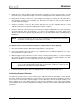
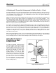


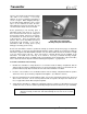
Table Of Contents
- Mark III Directional Drilling Locating System
- Table of Contents
- Table of Contents (Cont.)
- Table of Contents (Cont.)
- Safety Precautions and Warnings
- Safety Precautions and Warnings (Continued)
- Dear Customer:
- 3-3000-00b-F.pdf
- 3-3000-00c-F.pdf
- Receiver
- Display Window Icons
- On/Off
- Receiving the Transmitter’s Signals
- Clicking vs. Holding the Trigger
- Changing the Receiver’s Channel Setting
- Changing the Depth Measurement Units (English vs. Metric)
- Battery Status Display for Receiver and Transmitter
- Warning Tones for Transmitter Overheat
- Ultrasonic Function
- Calibrating the Receiver
- Using Depth Antenna Plumb Line to Mark Locate Points
- Finding Firmware Version
- 5.0 Series Firmware Functions
- Receiver
- 3-3000-00d-F.pdf
- 3-3000-00e-F.pdf
- 3-3000-00f-F.pdf
- 3-3000-00g-F.pdf
- 3-3000-00h-F.pdf
- 3-3000-00i-F.pdf
- 3-3000-00j-F.pdf
- Locating
- Locating Mode
- Locate Points (FNLP & RNLP) and Locate Line (PLL)
- Handling the Receiver
- Distance Between FNLP and RNLP Due to Depth, Pitch, and Topography
- Using Plus/Minus Indicators for Locating
- Locating the Transmitter from the Drill
- Locating the Transmitter from the Front
- Method for Confirming Position
- Locating on the Fly
- Off-Track Locating
- Splitting the Front and Rear Negative Locate Points
- Four-Turn Technique
- Calculating Depth Based on Distance Between FNLP & RNLP
- Running off Pitch or Calculating Depth from Pitch
- Transmitter’s Signal Shape
- Antenna Configuration
- Signal Reception
- Front and Rear Negative Locate Points
- Positive Locate Line Above Transmitter
- Locating
- 3-3000-00k-F.pdf
- 3-3000-00l-F.pdf
- 3-3000-00m-F.pdf
- 3-3000-00n-F.pdf
- 3-3000-00o-F.pdf
- 3-3000-00p-F.pdf

®
Transmitter
The temp dot should be white if the transmitter has not been exposed to excessive heat. If the temp dot
is silver or gray, it indicates the transmitter has been exposed to heat but not in excess of the speci-
fications. A black temp dot indicates the transmitter has been exposed to temperatures in excess of
104°C (220°F). The transmitter will shut off at about 80°C.
If the transmitter overheats, it may appear to operate normally; however, exposure to excessive tempera-
tures greatly increases the likelihood of inaccurate information and will contribute to premature failure of
the transmitter. The warranty does not apply to any transmitter that has been overheated or to any
transmitter where the temp dot has been removed. Avoid overheating by practicing proper drilling
techniques. Abrasive soils, clogged ports, inadequate mud flow, and poorly mixed mud can contribute
significantly to the risk of an overheated transmitter.
The transmitter temperature warnings are listed in the following table. These warnings apply for firmware
versions greater than 3.76. Drilling should be suspended when temperatures reach 35°C to permit
cooling.
Transmitter Temperature Warnings
Temperature Range Warning Signal
14°C and below
No audio or visual warnings.
15°C to 35°C One double tone with every 4°C increase in temperature.
36°C to 45°C Two double tones with every 4°C increase in temperature.
45°C to 60°C Three double tones with every 4°C increase in temperature.
60°C and above
Audible error tones (two long tones) and the bottom window will flash;
1999 may appear when the transmitter shuts down at about 80°C.
Sleep Mode (Automatic Shutoff)
The transmitter will shut down (go into “sleep” mode) to conserve battery power if it is stationary for 15
minutes. The transmitter sleep mode can be recognized on the receiver as “1999” in the bottom window
(no signal). To “wake up” the transmitter, simply rotate the drill string. For more information on 1999 in
the bottom window, see the Operational Tests Section, particularly “Transmitter Tests,” and the Trouble-
shooting Section.
Transmitters manufactured prior to January 1997 have what is called “12 o’clock shutoff.” This means
that when the transmitter is in the 12 o’clock position, the transmitter will shut off for 10 seconds and 1999
will be displayed in the bottom window of the receiver.
Verifying Proper Fit of Transmitter in Housing
Before installing a transmitter into a housing, read the information given below about how the transmitter
should fit into the housing. You may then proceed to the installation instructions that follow.
How Transmitter Should Fit in Housing
The transmitter must fit snugly into the housing. The transmitter has an index slot in the front end cap
that
fits onto the anti-roll pin (key) in the housing. Wrap the transmitter with tape or O-rings to eliminate
DigiTrak
®
Mark III Operator’s Manual 21