
User's Manual
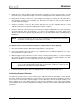
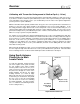


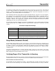
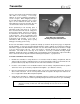
Table Of Contents
- Mark III Directional Drilling Locating System
- Table of Contents
- Table of Contents (Cont.)
- Table of Contents (Cont.)
- Safety Precautions and Warnings
- Safety Precautions and Warnings (Continued)
- Dear Customer:
- 3-3000-00b-F.pdf
- 3-3000-00c-F.pdf
- Receiver
- Display Window Icons
- On/Off
- Receiving the Transmitter’s Signals
- Clicking vs. Holding the Trigger
- Changing the Receiver’s Channel Setting
- Changing the Depth Measurement Units (English vs. Metric)
- Battery Status Display for Receiver and Transmitter
- Warning Tones for Transmitter Overheat
- Ultrasonic Function
- Calibrating the Receiver
- Using Depth Antenna Plumb Line to Mark Locate Points
- Finding Firmware Version
- 5.0 Series Firmware Functions
- Receiver
- 3-3000-00d-F.pdf
- 3-3000-00e-F.pdf
- 3-3000-00f-F.pdf
- 3-3000-00g-F.pdf
- 3-3000-00h-F.pdf
- 3-3000-00i-F.pdf
- 3-3000-00j-F.pdf
- Locating
- Locating Mode
- Locate Points (FNLP & RNLP) and Locate Line (PLL)
- Handling the Receiver
- Distance Between FNLP and RNLP Due to Depth, Pitch, and Topography
- Using Plus/Minus Indicators for Locating
- Locating the Transmitter from the Drill
- Locating the Transmitter from the Front
- Method for Confirming Position
- Locating on the Fly
- Off-Track Locating
- Splitting the Front and Rear Negative Locate Points
- Four-Turn Technique
- Calculating Depth Based on Distance Between FNLP & RNLP
- Running off Pitch or Calculating Depth from Pitch
- Transmitter’s Signal Shape
- Antenna Configuration
- Signal Reception
- Front and Rear Negative Locate Points
- Positive Locate Line Above Transmitter
- Locating
- 3-3000-00k-F.pdf
- 3-3000-00l-F.pdf
- 3-3000-00m-F.pdf
- 3-3000-00n-F.pdf
- 3-3000-00o-F.pdf
- 3-3000-00p-F.pdf
Transmitter
®
Transmitter roll positions are displayed digitally as a whole number from 1 through 12 in the top right
window with the receiver’s trigger released. The numbers correspond to the hour hand of a clock. At the
12 o’clock position, the transmitter is oriented with the index slot at the top. The tapered or flattened sur-
face of the drill head should be indexed to this position.
Batteries
All DCI transmitters (except the cable transmitter) are powered by C-cell alkaline batteries (see Trans-
mitter Specifications at the end of this section). The long-range transmitters, including the sensitive-pitch
transmitters, have a 4 C-cell option for longer bores. The status of the batteries in the transmitter can be
viewed (in percent life remaining) using the receiver’s display (see “Battery Status Display” below). The
cable transmitter requires an above-ground power supply (see Transmitter Section).
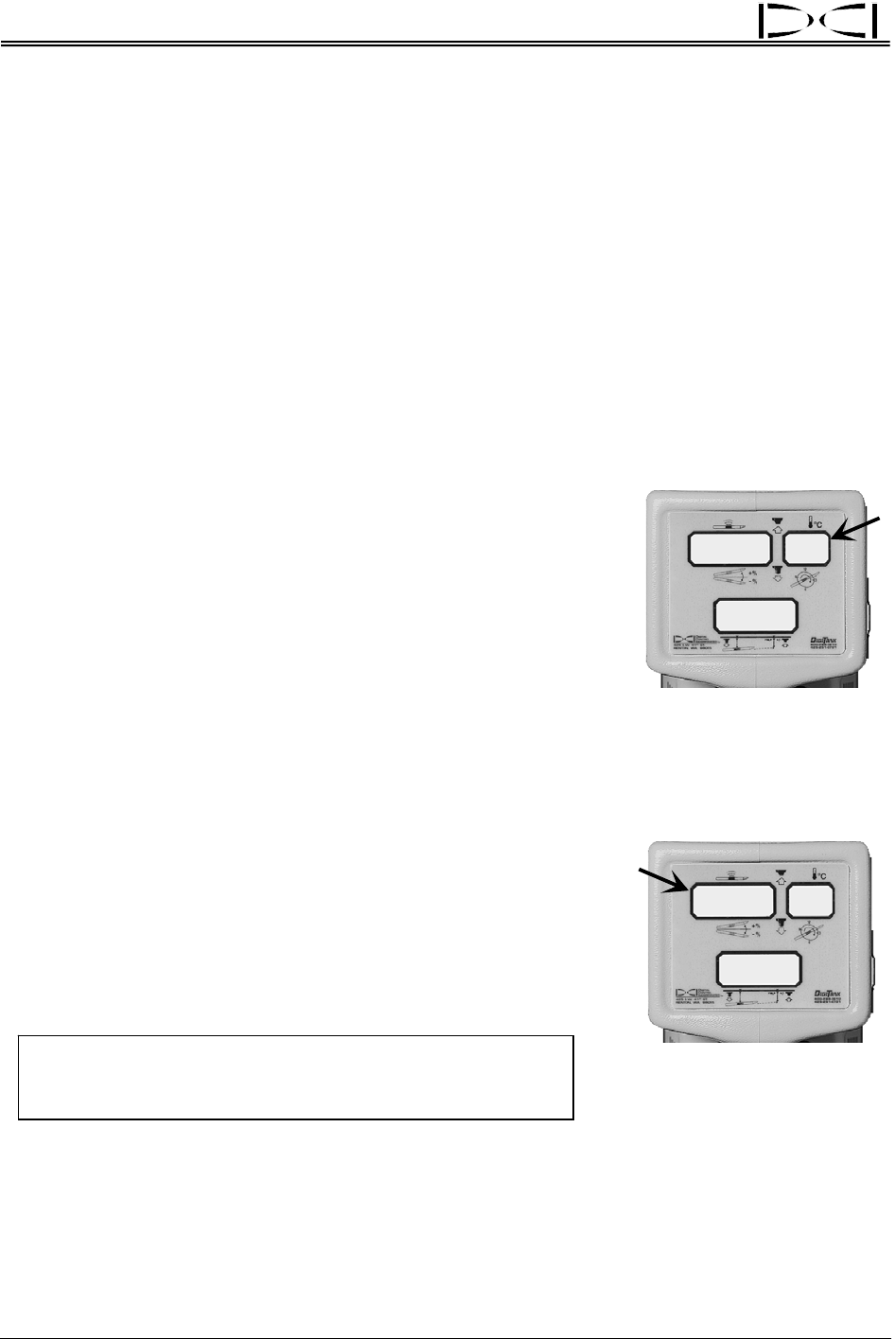
Temperature Display
6
I
9
I
26
22
+
~
Transmitter Temperature
Display (Flashing)
Transmitter temperature is displayed in degrees Celsius. Every 4°C
increase in the transmitter’s temperature will flash for 2 seconds in the
top right window of the receiver and the remote display. The receiver
will also sound audible tones that increase in intensity as the
transmitter’s temperature increases. When the remote display has a
DataLog module attached, the transmitter’s temperature increase
tones will be heard at the drill. To manually view the temperature of
the transmitter, simply hold in the receiver’s trigger; the temperature
will flash in the top right window. Receivers with pre-5.0 series
firmware will display the temperature in the top right window while the
trigger is held in, but it will not flash. To view the transmitter tempera-
ture at the drill, see the Remote Display Section.
Battery Status Display
90
56
90
BAT
Transmitter Battery Status
in Percent Remaining Life
The percent of battery life remaining in the transmitter is displayed in
the top left window for 2 seconds upon releasing a held-in trigger. The
transmitter’s battery status in percent remaining life is displayed as
100, 90, 75, 50, 25, 10, 5, or 0. (The receiver’s battery status in
percent remaining life is also displayed during this 2-second interval in
the top right window as 99, 90, 75, 50, 25, 10, 5, or 0.) If the word
BAT occurs in the top left window when not viewing the transmitter’s
battery status, the transmitter batteries must be replaced.
NOTE: Neither the temperature nor the battery status will
be available until 4 minutes after initial start-up for
receivers with 5.0 series or later firmware.
Temperature Overheat
All transmitters have a temperature overheat indicator (temp dot) that has an outer yellow ring with a 1/8-
inch (3-mm) white dot in the center. This temp dot is located on the stainless-steel front end cap. On
older transmitters, the temp dot is located inside the battery compartment next to the battery terminal.
20 DigiTrak
®
Mark III Operator’s Manual