
User's Manual
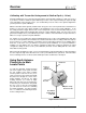

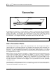

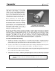
Table Of Contents
- Mark III Directional Drilling Locating System
- Table of Contents
- Table of Contents (Cont.)
- Table of Contents (Cont.)
- Safety Precautions and Warnings
- Safety Precautions and Warnings (Continued)
- Dear Customer:
- 3-3000-00b-F.pdf
- 3-3000-00c-F.pdf
- Receiver
- Display Window Icons
- On/Off
- Receiving the Transmitter’s Signals
- Clicking vs. Holding the Trigger
- Changing the Receiver’s Channel Setting
- Changing the Depth Measurement Units (English vs. Metric)
- Battery Status Display for Receiver and Transmitter
- Warning Tones for Transmitter Overheat
- Ultrasonic Function
- Calibrating the Receiver
- Using Depth Antenna Plumb Line to Mark Locate Points
- Finding Firmware Version
- 5.0 Series Firmware Functions
- Receiver
- 3-3000-00d-F.pdf
- 3-3000-00e-F.pdf
- 3-3000-00f-F.pdf
- 3-3000-00g-F.pdf
- 3-3000-00h-F.pdf
- 3-3000-00i-F.pdf
- 3-3000-00j-F.pdf
- Locating
- Locating Mode
- Locate Points (FNLP & RNLP) and Locate Line (PLL)
- Handling the Receiver
- Distance Between FNLP and RNLP Due to Depth, Pitch, and Topography
- Using Plus/Minus Indicators for Locating
- Locating the Transmitter from the Drill
- Locating the Transmitter from the Front
- Method for Confirming Position
- Locating on the Fly
- Off-Track Locating
- Splitting the Front and Rear Negative Locate Points
- Four-Turn Technique
- Calculating Depth Based on Distance Between FNLP & RNLP
- Running off Pitch or Calculating Depth from Pitch
- Transmitter’s Signal Shape
- Antenna Configuration
- Signal Reception
- Front and Rear Negative Locate Points
- Positive Locate Line Above Transmitter
- Locating
- 3-3000-00k-F.pdf
- 3-3000-00l-F.pdf
- 3-3000-00m-F.pdf
- 3-3000-00n-F.pdf
- 3-3000-00o-F.pdf
- 3-3000-00p-F.pdf
®
DIGITAL CONTROL INCORPORATED
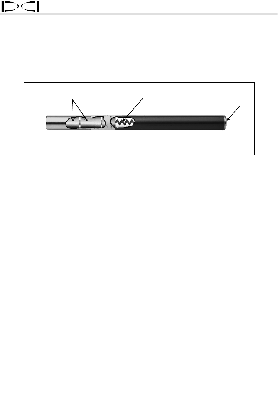
Transmitter
Front
Back
Batteries Antenna
Index Slot
DigiTrak Transmitter
A transmitter (also referred to as a sonde, beacon, or probe) is a device that emits electromagnetic
signals at radio frequencies and fits inside the tool housing. It transmits information regarding its location,
position, and heading. The transmitter emits signals that the receiver “hears” and converts into the
information shown in the three display windows. The range of a transmitter depends upon its type. For
more information, see the DigiTrak Transmitter Specifications table at the end of this section.
NOTE: The range of any transmitter with any DCI receiver is dependent upon the amount of inter-
ference at a job site. The range decreases as interference increases.
How a Transmitter Works
The transmitter emits two types of signals, both at approximately 33 kHz. The first signal is the depth or
signal strength. The second signal sends pitch, roll, and battery and temperature status information. The
pitch/roll signal has a wider bandwidth than the depth signal and occasionally may be more susceptible to
interference. For more information about interference and transmitter signal interruption, see the Signal
Interference Section, the Troubleshooting Section, and “Electrical Interference/Background Noise Check”
in the Signal Interference Section.
With the trigger released, verify that the transmitter is sending adequate pitch and roll information to the
receiver—the top left window of the receiver will flash a squiggle (“~”) every 2.5 seconds. It is important
to wait for two consecutive squiggles with the same pitch and roll information before relying on the infor-
mation to give any steering commands. Waiting assures confirmation of an accurate reading. As the
transmitter reaches its maximum range, the squiggles will become less frequent than every 2.5 seconds.
For further information on pitch/roll and the squiggle, see the Operational Tests Section (particularly
“Transmitter Tests”).
Transmitter pitch is displayed in percent slope as 1% increments or 0.1% increments (if using a sensitive-
pitch transmitter) in the top left window of the receiver with the trigger released. For more information see
“Sensitive-Pitch Transmitters” later in this section.
DigiTrak
®
Mark III Operator’s Manual 19