
User's Manual
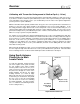


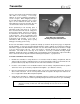
Table Of Contents
- Mark III Directional Drilling Locating System
- Table of Contents
- Table of Contents (Cont.)
- Table of Contents (Cont.)
- Safety Precautions and Warnings
- Safety Precautions and Warnings (Continued)
- Dear Customer:
- 3-3000-00b-F.pdf
- 3-3000-00c-F.pdf
- Receiver
- Display Window Icons
- On/Off
- Receiving the Transmitter’s Signals
- Clicking vs. Holding the Trigger
- Changing the Receiver’s Channel Setting
- Changing the Depth Measurement Units (English vs. Metric)
- Battery Status Display for Receiver and Transmitter
- Warning Tones for Transmitter Overheat
- Ultrasonic Function
- Calibrating the Receiver
- Using Depth Antenna Plumb Line to Mark Locate Points
- Finding Firmware Version
- 5.0 Series Firmware Functions
- Receiver
- 3-3000-00d-F.pdf
- 3-3000-00e-F.pdf
- 3-3000-00f-F.pdf
- 3-3000-00g-F.pdf
- 3-3000-00h-F.pdf
- 3-3000-00i-F.pdf
- 3-3000-00j-F.pdf
- Locating
- Locating Mode
- Locate Points (FNLP & RNLP) and Locate Line (PLL)
- Handling the Receiver
- Distance Between FNLP and RNLP Due to Depth, Pitch, and Topography
- Using Plus/Minus Indicators for Locating
- Locating the Transmitter from the Drill
- Locating the Transmitter from the Front
- Method for Confirming Position
- Locating on the Fly
- Off-Track Locating
- Splitting the Front and Rear Negative Locate Points
- Four-Turn Technique
- Calculating Depth Based on Distance Between FNLP & RNLP
- Running off Pitch or Calculating Depth from Pitch
- Transmitter’s Signal Shape
- Antenna Configuration
- Signal Reception
- Front and Rear Negative Locate Points
- Positive Locate Line Above Transmitter
- Locating
- 3-3000-00k-F.pdf
- 3-3000-00l-F.pdf
- 3-3000-00m-F.pdf
- 3-3000-00n-F.pdf
- 3-3000-00o-F.pdf
- 3-3000-00p-F.pdf
Receiver
®
Calibrating with Transmitter Underground at Shallow Depth (< 10 feet)
Should recalibration be necessary when the transmitter is below ground at depths less than 10 ft (3 m), it
is possible to conduct a modified 1-point calibration procedure. This requires knowing the signal strength
of the transmitter in the housing at 10 ft. (You should always note the value of the signal strength when
you first perform a 1-point calibration.)
With the transmitter below ground (shallower than 10 ft), place the receiver parallel to the transmitter at a
distance to cause the same signal strength as noted during the most recent 1-point calibration. To do
this, simply hold in the trigger and move the receiver away from or closer to the transmitter until you see a
signal strength reading (top left window) that equals the 1-point calibration signal. Set the receiver on the
ground, and complete the 1-point calibration procedure. However, if the transmitter is deeper than 10 ft, it
will be necessary to perform a 2-point calibration.
For example, if you noted that the signal strength during the most recent 1-point calibration was 560, then
move the receiver parallel to the transmitter to a distance that will result in a reading of 560 and complete
the procedure for a 1-point calibration. Remember, this procedure will not work if you are drilling deeper
than 10 ft. If this is the case, you will have to perform a 2-point calibration, or, if a spare transmitter is
available, you can calibrate to it at a distance equivalent to 560 points of signal (or whatever the signal
strength was during the most recent 1-point calibration) and then resume drilling with the same trans-
mitter that is below ground.
When using this modified procedure, you are assuming that the in-ground transmitter is still performing at
the same signal strength it was when the most recent 1-point calibration was performed. If the transmitter
has been damaged or has overheated, this modified procedure should not be relied upon.
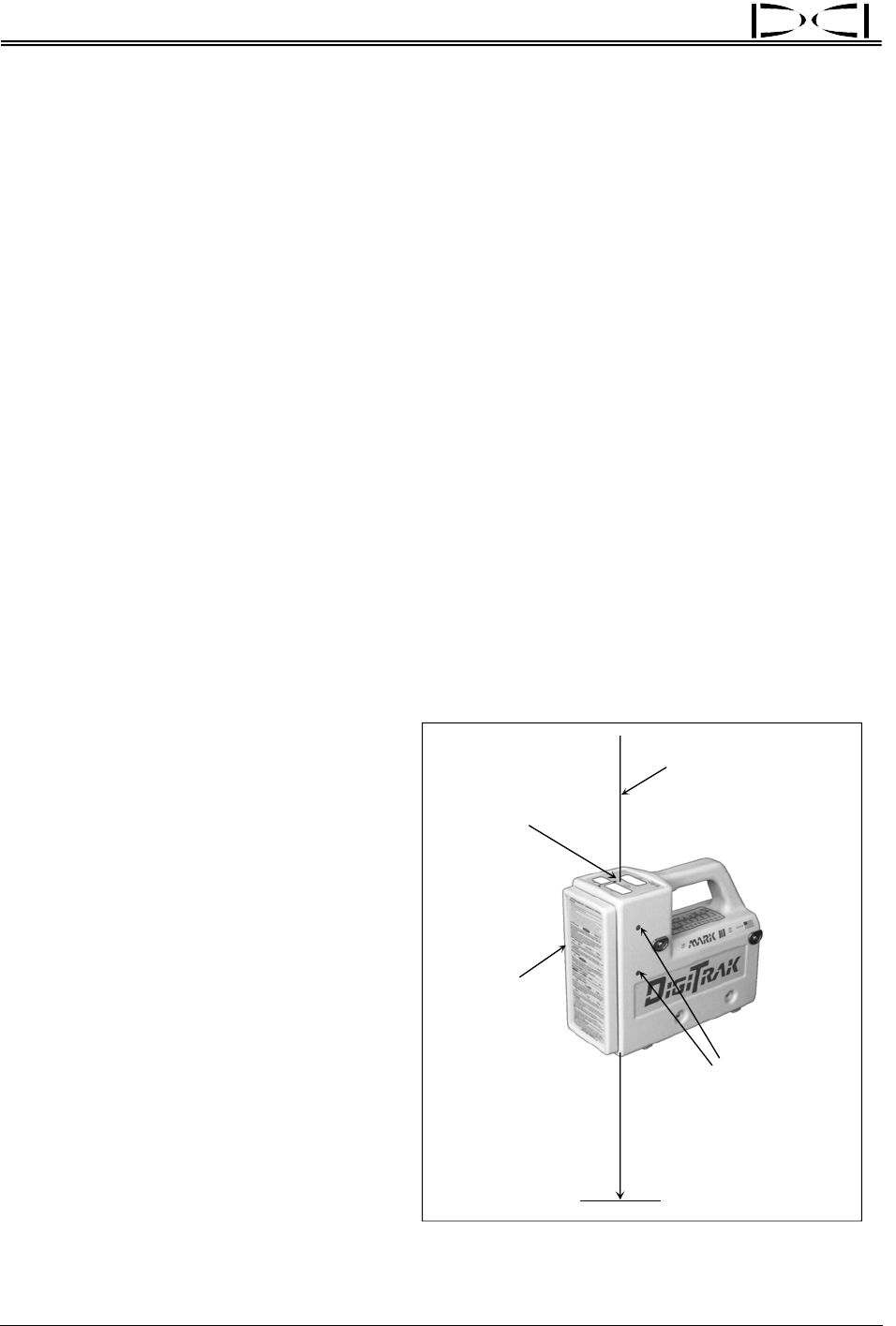
Using Depth Antenna
Plumb Line to Mark
Locate Points
Center of
Display
Windows
Plumb Line
Depth/Locating
Antenna Screws
Place Marker
Straight Down
on Ground
Front of
Receiver
Depth Antenna Plumb Line
To mark the important locating positions
(the front negative locate point or FNLP;
the rear negative locate point or RNLP;
and the positive locate line or PLL) accu-
rately,
you must use the vertical axis (plumb
line) that runs through the center of the
display windows and bisects the depth/
locating antennas (see sketch at right).
Where this axis intersects the ground is the
location that you should mark. This plumb
line also serves as the axis around which
you can rotate the receiver for confirming
the FNLP and RNLP. (For more informa-
tion, see “Method for Confirming Position”
in the Locating Section.)
16 DigiTrak
®
Mark III Operator’s Manual