
User's Manual
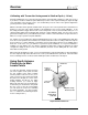

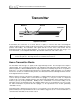

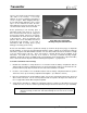
Table Of Contents
- Mark III Directional Drilling Locating System
- Table of Contents
- Table of Contents (Cont.)
- Table of Contents (Cont.)
- Safety Precautions and Warnings
- Safety Precautions and Warnings (Continued)
- Dear Customer:
- 3-3000-00b-F.pdf
- 3-3000-00c-F.pdf
- Receiver
- Display Window Icons
- On/Off
- Receiving the Transmitter’s Signals
- Clicking vs. Holding the Trigger
- Changing the Receiver’s Channel Setting
- Changing the Depth Measurement Units (English vs. Metric)
- Battery Status Display for Receiver and Transmitter
- Warning Tones for Transmitter Overheat
- Ultrasonic Function
- Calibrating the Receiver
- Using Depth Antenna Plumb Line to Mark Locate Points
- Finding Firmware Version
- 5.0 Series Firmware Functions
- Receiver
- 3-3000-00d-F.pdf
- 3-3000-00e-F.pdf
- 3-3000-00f-F.pdf
- 3-3000-00g-F.pdf
- 3-3000-00h-F.pdf
- 3-3000-00i-F.pdf
- 3-3000-00j-F.pdf
- Locating
- Locating Mode
- Locate Points (FNLP & RNLP) and Locate Line (PLL)
- Handling the Receiver
- Distance Between FNLP and RNLP Due to Depth, Pitch, and Topography
- Using Plus/Minus Indicators for Locating
- Locating the Transmitter from the Drill
- Locating the Transmitter from the Front
- Method for Confirming Position
- Locating on the Fly
- Off-Track Locating
- Splitting the Front and Rear Negative Locate Points
- Four-Turn Technique
- Calculating Depth Based on Distance Between FNLP & RNLP
- Running off Pitch or Calculating Depth from Pitch
- Transmitter’s Signal Shape
- Antenna Configuration
- Signal Reception
- Front and Rear Negative Locate Points
- Positive Locate Line Above Transmitter
- Locating
- 3-3000-00k-F.pdf
- 3-3000-00l-F.pdf
- 3-3000-00m-F.pdf
- 3-3000-00n-F.pdf
- 3-3000-00o-F.pdf
- 3-3000-00p-F.pdf
®
Receiver
Calibrating the Receiver
There are two different calibration methods: 1-point and 2-point. The 1-point calibration is performed
with the transmitter in the housing parallel to and 10 ft 5 in. (3.18 m) from the receiver, as described
below. A 2-point calibration is generally performed when the transmitter is below ground and it is not
possible to perform a 1-point calibration.
Calibration is necessary prior to first time use and when any of the following occur:
¾ The transmitter is changed.
¾ The receiver is changed.
¾ The housing/drill tool is changed.
Do not calibrate if:
¾ You are within 10 ft (3 m) of metal structures, such as steel pipe, chain link fence, metal siding, con-
struction equipment, or automobiles.
¾ The receiver is over rebar or underground utilities.
¾ The receiver is in the vicinity of excessive electrical interference (see “Electrical Interference/
Background Noise Check” in the Signal Interference Section).
¾ The transmitter is not installed into the housing.
¾ The transmitter is not turned on.
NOTE: Calibration should be checked at 10 ft 5 in. (3.18 m) daily and before every use. Calibra-
tion only affects the depth/distance reading, not pitch or roll.
1-Point Calibration Procedure
1. Confirm the lack of interference (see Electrical Interference/Background Noise” Check in the Signal
Interference Section). Make sure there are no other active transmitters within range of the receiver.
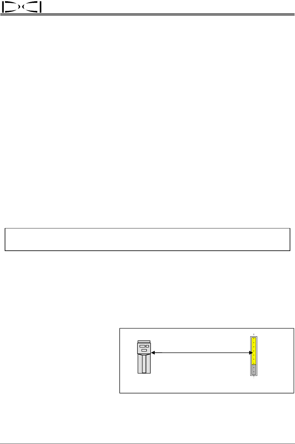
2. Place an operating transmitter inside the housing on level ground.
3. After the receiver has completed the start-up sequence, place it exactly 10 ft 5 in. (3.18 m) from the
housing as shown in the sketch (a tape measure must be used for accuracy; measure from centerline
of transmitter to inside edge of re-
ceiver). Hold in the trigger to con-
firm a stable signal, then release
the trigger; note signal strength
reading. The signal strength must
be at least
250 points for proper
calibration. If your reading is less
than 250, the transmitter may be
malfunctioning, and you should call
DCI.
10 ft 5 in. (3.18 m)
Recei
v
e
r
Transmitte
r
(Inside
Housing)
Transmitter
Centerline
Determining 1-Point Calibration Signal
DigiTrak
®
Mark III Operator’s Manual 13