
User's Manual

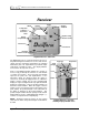
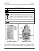
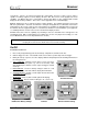
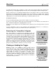
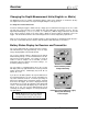
Table Of Contents
- Mark III Directional Drilling Locating System
- Table of Contents
- Table of Contents (Cont.)
- Table of Contents (Cont.)
- Safety Precautions and Warnings
- Safety Precautions and Warnings (Continued)
- Dear Customer:
- 3-3000-00b-F.pdf
- 3-3000-00c-F.pdf
- Receiver
- Display Window Icons
- On/Off
- Receiving the Transmitter’s Signals
- Clicking vs. Holding the Trigger
- Changing the Receiver’s Channel Setting
- Changing the Depth Measurement Units (English vs. Metric)
- Battery Status Display for Receiver and Transmitter
- Warning Tones for Transmitter Overheat
- Ultrasonic Function
- Calibrating the Receiver
- Using Depth Antenna Plumb Line to Mark Locate Points
- Finding Firmware Version
- 5.0 Series Firmware Functions
- Receiver
- 3-3000-00d-F.pdf
- 3-3000-00e-F.pdf
- 3-3000-00f-F.pdf
- 3-3000-00g-F.pdf
- 3-3000-00h-F.pdf
- 3-3000-00i-F.pdf
- 3-3000-00j-F.pdf
- Locating
- Locating Mode
- Locate Points (FNLP & RNLP) and Locate Line (PLL)
- Handling the Receiver
- Distance Between FNLP and RNLP Due to Depth, Pitch, and Topography
- Using Plus/Minus Indicators for Locating
- Locating the Transmitter from the Drill
- Locating the Transmitter from the Front
- Method for Confirming Position
- Locating on the Fly
- Off-Track Locating
- Splitting the Front and Rear Negative Locate Points
- Four-Turn Technique
- Calculating Depth Based on Distance Between FNLP & RNLP
- Running off Pitch or Calculating Depth from Pitch
- Transmitter’s Signal Shape
- Antenna Configuration
- Signal Reception
- Front and Rear Negative Locate Points
- Positive Locate Line Above Transmitter
- Locating
- 3-3000-00k-F.pdf
- 3-3000-00l-F.pdf
- 3-3000-00m-F.pdf
- 3-3000-00n-F.pdf
- 3-3000-00o-F.pdf
- 3-3000-00p-F.pdf
®
Receiver
Warning Tones for Transmitter Overheat
Beginning with firmware version 3.76, the DigiTrak Receiver will emit a series of increasing warning tones
to signal transmitter overheating as follows:
Temperature Range Warning Signal
14°C and below
No audio or visual warnings.
15°C to 35°C One double tone with every 4°C increase in temperature.
36°C to 45°C Two double tones with every 4°C increase in temperature.
45°C to 60°C Three double tones with every 4°C increase in temperature.
60°C and above
Audible error tones (two long tones) and the bottom window will flash;
1999 may appear when the transmitter shuts down at about 80°C.
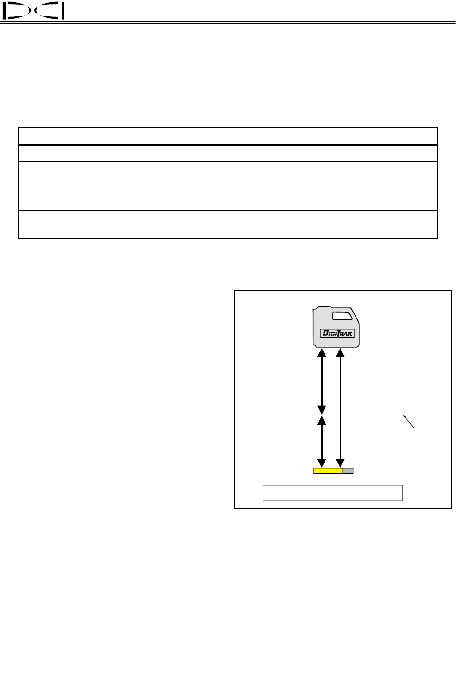
Ultrasonic Function
Ultrasonic
Measurement
Depth
Magnetic
Distance
Surface of
Ground
Depth = Magnetic – Ultrasonic
Use of Ultrasonic Measurement
To Determine Actual Depth
The ultrasonic function measures the receiver’s
elevation above the ground and subtracts that
distance from the total magnetic distance to
calculate the depth of the transmitter below the
ground’s surface. The ultrasonic function is de-
signed to help the operator observe the depth
reading while maintaining separation between
the receiver’s antennas and potential sources of
interference. An ultrasonic measurement can
only be taken after start-up is completed.
The ultrasonic function is particularly useful when:
¾ Locating over obstacles.
¾ Obtaining adequate separation from utilities
in the ground or rebar interference.
¾ Locating above water.
¾ Verifying calibration when the transmitter is
underground.
¾ Recalibrating in the ground (see
“2-Point
Calibration” below).
The ultrasonic measurement is made by emitting and receiving signals from the two small round holes/
where transducers are mounted on the bottom of the receiver. When the trigger is clicked, one
transducer emits a high-frequency sound wave that travels to the nearest surface and bounces back to be
received by the other transducer. The time required for the signal to return is used to calculate the
distance to the ground. The operating range of the ultrasonic measurement is between 12 inches (30 cm)
and 90 inches (230 cm). The ultrasonic measurement is displayed in the bottom window for 2 seconds
after the trigger is clicked one time.
DigiTrak
®
Mark III Operator’s Manual 11