
User's Manual
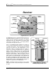
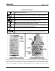
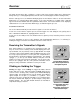
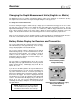
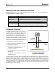
Table Of Contents
- Mark III Directional Drilling Locating System
- Table of Contents
- Table of Contents (Cont.)
- Table of Contents (Cont.)
- Safety Precautions and Warnings
- Safety Precautions and Warnings (Continued)
- Dear Customer:
- 3-3000-00b-F.pdf
- 3-3000-00c-F.pdf
- Receiver
- Display Window Icons
- On/Off
- Receiving the Transmitter’s Signals
- Clicking vs. Holding the Trigger
- Changing the Receiver’s Channel Setting
- Changing the Depth Measurement Units (English vs. Metric)
- Battery Status Display for Receiver and Transmitter
- Warning Tones for Transmitter Overheat
- Ultrasonic Function
- Calibrating the Receiver
- Using Depth Antenna Plumb Line to Mark Locate Points
- Finding Firmware Version
- 5.0 Series Firmware Functions
- Receiver
- 3-3000-00d-F.pdf
- 3-3000-00e-F.pdf
- 3-3000-00f-F.pdf
- 3-3000-00g-F.pdf
- 3-3000-00h-F.pdf
- 3-3000-00i-F.pdf
- 3-3000-00j-F.pdf
- Locating
- Locating Mode
- Locate Points (FNLP & RNLP) and Locate Line (PLL)
- Handling the Receiver
- Distance Between FNLP and RNLP Due to Depth, Pitch, and Topography
- Using Plus/Minus Indicators for Locating
- Locating the Transmitter from the Drill
- Locating the Transmitter from the Front
- Method for Confirming Position
- Locating on the Fly
- Off-Track Locating
- Splitting the Front and Rear Negative Locate Points
- Four-Turn Technique
- Calculating Depth Based on Distance Between FNLP & RNLP
- Running off Pitch or Calculating Depth from Pitch
- Transmitter’s Signal Shape
- Antenna Configuration
- Signal Reception
- Front and Rear Negative Locate Points
- Positive Locate Line Above Transmitter
- Locating
- 3-3000-00k-F.pdf
- 3-3000-00l-F.pdf
- 3-3000-00m-F.pdf
- 3-3000-00n-F.pdf
- 3-3000-00o-F.pdf
- 3-3000-00p-F.pdf

®
Receiver
For receivers that have pre-5.0 series firmware, the bottom window will continue to display the receiver’s
distance from the transmitter in the bottom window, not the predicted depth. (For more information, see
“5.0 Series Firmware Functions” in this section or see the Locating Section.)
Any time the trigger is clicked (pushed in and released in less than ½ second), the receiver will initiate an
ultrasonic measurement, which is also referred to as the height-above-ground measurement. This
measurement is the distance between the receiver and the ground, which is measured by the ultrasonic
transducers on the bottom of the receiver. An ultrasonic measurement can be taken an unlimited number
of times (reset) without affecting the receiver’s calibration. The ultrasonic function is independent of the
transmitter and measures the receiver’s elevation above the ground. The ultrasonic distance is
automatically subtracted from the distance to the transmitter to provide the operator with a display of the
transmitter’s depth/distance below the ground’s surface. The ultrasonics were designed to reduce the
effects of interference by increasing the separation between the interference source in the ground (e.g.,
rebar) and the receiver. (For more information, see “Ultrasonic Function” later in this section.)
Changing the Receiver’s Channel Setting
If using a remote display unit, the receiver and remote display unit must each be set to the same channel.
Changing the receiver’s channel selection can only be done at start-up.
To change the channel:
At the end of the start-up sequence, the bottom window will display the current remote channel setting (0,
1, 2, 3, or 4) for 2 seconds. During this time, the trigger can be clicked to change the channel to the
desired setting. This setting will remain until you change it. Replacing the batteries in any piece of
equipment will not affect the current channel setting, the ultrasonic setting, or the receiver’s calibration.
NOTE: A zero (0) remote channel setting indicates that the receiver’s telemetry signal is shut off and no
signal is being sent to the remote display unit. “Dashes” will appear across the three display windows on
the remote display to indicate no signal is being received. Setting the receiver to channel 0 can be done
to conserve the receiver’s battery (see Remote Display Section).
The DigiTrak System uses ultrahigh-frequency telemetry to communicate between the receiver and the
remote display. Both the receiver and the remote display must have the same type of telemetry to
communicate properly.
DigiTrak
®
Mark III Operator’s Manual 9