
User's Manual

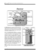
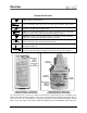
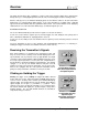
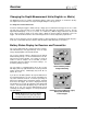
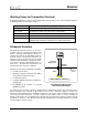
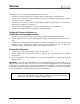
Table Of Contents
- Mark III Directional Drilling Locating System
- Table of Contents
- Table of Contents (Cont.)
- Table of Contents (Cont.)
- Safety Precautions and Warnings
- Safety Precautions and Warnings (Continued)
- Dear Customer:
- 3-3000-00b-F.pdf
- 3-3000-00c-F.pdf
- Receiver
- Display Window Icons
- On/Off
- Receiving the Transmitter’s Signals
- Clicking vs. Holding the Trigger
- Changing the Receiver’s Channel Setting
- Changing the Depth Measurement Units (English vs. Metric)
- Battery Status Display for Receiver and Transmitter
- Warning Tones for Transmitter Overheat
- Ultrasonic Function
- Calibrating the Receiver
- Using Depth Antenna Plumb Line to Mark Locate Points
- Finding Firmware Version
- 5.0 Series Firmware Functions
- Receiver
- 3-3000-00d-F.pdf
- 3-3000-00e-F.pdf
- 3-3000-00f-F.pdf
- 3-3000-00g-F.pdf
- 3-3000-00h-F.pdf
- 3-3000-00i-F.pdf
- 3-3000-00j-F.pdf
- Locating
- Locating Mode
- Locate Points (FNLP & RNLP) and Locate Line (PLL)
- Handling the Receiver
- Distance Between FNLP and RNLP Due to Depth, Pitch, and Topography
- Using Plus/Minus Indicators for Locating
- Locating the Transmitter from the Drill
- Locating the Transmitter from the Front
- Method for Confirming Position
- Locating on the Fly
- Off-Track Locating
- Splitting the Front and Rear Negative Locate Points
- Four-Turn Technique
- Calculating Depth Based on Distance Between FNLP & RNLP
- Running off Pitch or Calculating Depth from Pitch
- Transmitter’s Signal Shape
- Antenna Configuration
- Signal Reception
- Front and Rear Negative Locate Points
- Positive Locate Line Above Transmitter
- Locating
- 3-3000-00k-F.pdf
- 3-3000-00l-F.pdf
- 3-3000-00m-F.pdf
- 3-3000-00n-F.pdf
- 3-3000-00o-F.pdf
- 3-3000-00p-F.pdf
Receiver
®
Display Window Icons
Trigger down – Trigger is released; display windows show pitch, roll, and
distance/depth of the transmitter.
+%
- %
Pitch – Numbers from 0% to ±100% show the inclination of the transmitter with
respect to horizontal; 100% represents a 45° angle (top left window, trigger down).
12
3
9
6
Roll – Numbers from 1 to 12 show the roll position (1 o’clock to 12 o’clock) of the
transmitter (top right window, trigger down).
x
Depth – The bottom window displays the depth or slant distance of the transmitter
with respect to the surface of the ground when the trigger is down.
Trigger up – Trigger is held in; display windows show signal strength, transmitter
temperature, and predicted depth when operator is at FNLP.
Signal strength – Numbers from 0 to 999 are displayed to show the strength of the
signal from the transmitter (top left window, trigger up).
o
C
Transmitter temperature – Temperature of the transmitter in degrees Celsius (top
right window, trigger up).
FNLP
x
+/
–
Predicted depth – The bottom window displays the predicted depth of the
transmitter at the FNLP when the trigger is up and the receiver is at the FNLP.
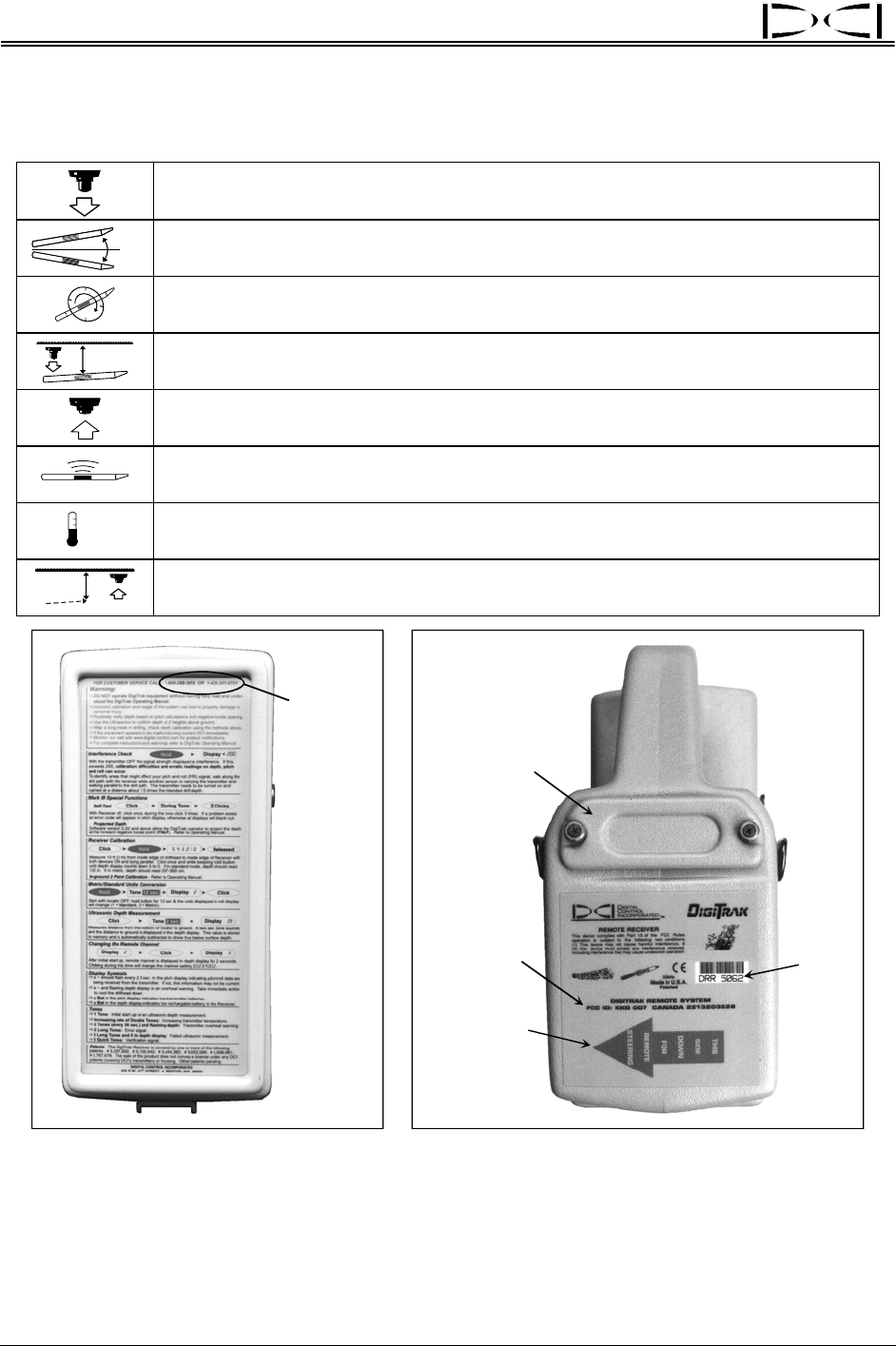
Customer
Service
Phone
Numbers:
800-288-3610
and
425-251-0559
Battery
Compartment
Orange Arrow
Indicates
Remote
Capability
Serial
Number
Telemetry
Information
DigiTrak Receiver – Front Panel DigiTrak Receiver – Back Side
Showing Condensed Instructions Showing Identification Information
The front panel of the receiver has condensed instructions for quick field reference and DCI’s phone
numbers for troubleshooting assistance. There is also a sticker under the handle for temperature and dis-
tance conversions. The serial number is located on the back panel of the unit below the battery compart-
ment; it is preceded by the letters DR or DRR (for DigiTrak Receiver and DigiTrak Remote Receiver,
6 DigiTrak
®
Mark III Operator’s Manual