
Inc Sound Module Decoder - Manual

© 2017 Digitrax, Inc.
www.digitrax.com- 61 -
9.7 Troubleshooting FX effects
Common problems with FX set up are:
Trying to program a decoder for FX when the decoder does not sup-
port FX. Be sure the decoder you are installing has FX features.
Digitrax introduced FX in the summer of 1995 so if your decoder
was made before then it does not have FX capability. Since 1995 all
Digitrax premium decoders have included FX. Digitrax standard and
economy decoders do not have FX features.
FX effects don’t work as expected. Review the qualifiers you set up for
the effect. For example, if the effect is set up to come on only when
F1 and F0 are active and the loco is headed in the forward direction,
be sure you have met those conditions.
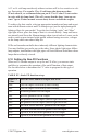
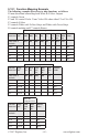
9.8 Setting Up A Master Light Switch with FX
3
Decoders
For FX
3
decoders F0 can be used as a master light switch to turn off all lights
in the locomotive when F0 if OFF. To do this, set up all functions so they are
ON when F0 is ON and OFF when F0 is OFF. See TABLE XII for master
light switch set up.
9.9 Lamp Selection For Prototypical Lighting Results
At the heart of realistic FX lighting effects is the selection of lamps that can
give realistic looking results. Adjusting the brightness and locating the lamps in
the model also have an effect on how realistic your installation will look.
Most modern locomotives use LEDs for lighting and over time the LEDs in
current use have gotten more realistic looking. Digitrax recommends using
incandescent lamps to achieve the most realistic lighting effects. Digitrax
Series 6 decoders give you the option to select whether to use the FX algorithm
that is best for LEDs or the one that is best for incandescent bulbs, this is set in
CV61 and is set to the LED setting at the factory since most current production
locos use LEDs.
For 1.5V lamps, a current setting resistor MUST be used in series with the +
voltage supply to the lamp. This is usually installed in series with the “white
or yellow” wire. For example operating on the DB150 “N scale” setting with
12V DCC signal on the track, we have found a resistor of approximately 500
ohms 1/4 watt gives 1.2mm lamps a good brightness level without shortening
their lives too much. With 1.5V lamps, the brightness level is very sensitive to
the resistor value. As you change the value of the resistor you will see that the
related change in lamp brightness is “non linear.” Running a few volts higher
will create too bright a light and degrade lamp life and lower voltages may
result in very dim lights.