
Inc Kato SD40-2 N Scale Mobile Decoder - Manual


©2010 Digitrax, Inc. www.digitrax.com 3
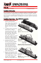
Installation Notes:
1. Do not exceed the decoder’s 500mA total function output rating.
2. To use a function output with an inductive (coil) type load, see the Digitrax
Decoder Manual for more information to avoid damage to the decoder.
3. See the Digitrax Decoder Manual for full details of wiring 12-16V lamps,
1.5V lamps, and LEDs. Lamps that draw more than 80 mA when running
require a 22 ohm 1/4 watt resistor in series with the directional light func-
tion lead to protect the decoder.
Customizing Your Decoder
Your Digitrax decoder is ready to run and will operate using address 03 with no
additional programming. For a more prototypical railroading experience, your
decoder can be customized for your specific locomotive by programming some
of the Configuration Variables, or CVs, available. See the Digitrax Decoder
Manual or the Digitrax web site for more information.
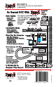
Changing the Decoder Address
The first CV most people change is the decoder address so that the loco can be
independently controlled with it’s own unique address. All Digitrax decoders
are shipped with CV01 (AD2), the two digit address, set to 03. See your Starter
Set Manual for complete programming instructions. Following is a brief
description of how to change the decoder address with a DT series throttles.
2443 Transmitter RD
T
850-872-9890
Panama City, FL 32404
F
850-872-9557
www.digitrax.com