
User Guide

Digitech VTP-1 Owner’s Manual
Table of Contents
Introduction
.................................................................................1
Warranty ......................................................................................2
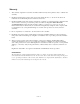
Connection Examples ...........................................................3
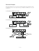
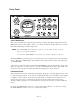
Rear Panel .................................................................................4
Wiring Scheme ..........................................................................4
Mic Input ...................................................................................4
Line Inputs.................................................................................4
Insert Loop ................................................................................5
Send ...........................................................................................5
Return ........................................................................................5
Digital Outputs ..........................................................................5
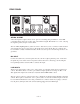
Front Panel.................................................................................6
Post Trim ...................................................................................6
Pre Gain.....................................................................................6
The VU Meter and CLIP LED..................................................7
The EQ section..........................................................................7
EQ In/Out switch.......................................................................8
Lo Cut switch ............................................................................8
Mic/Line Input switch ...............................................................8
Phase Reverse switch ................................................................9
20 dB Pad ..................................................................................9
+48V phantom power switch ....................................................9
DIGITAL OUTPUT Section .....................................................9
FORMAT Switch ................................................................9
SAMPLE RATE Switch .....................................................9
Appendix
Signal Flow Diagram .................................................................i
Specifications ............................................................................ii