
User Guide

••• 8 •••
Boosting frequencies adds gain and you may find that this lights the CLIP LED. If this
occurs, reduce the level with the PRE GAIN control or POST TRIM.
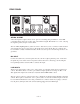
EQ In/Out switch
This switch removes the entire EQ circuit from the signal path. This is useful if you want to con-
firm that your EQ modifications are an improvement on the non-EQ’d signal. If you are not plan-
ning on using the EQ, this switch should be left in the “Out” position.
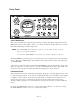
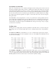
LO-CUT switch
This switch places a steep 12 dB per octave shelving circuit in the signal path with a knee frequen-
cy of 75 Hz. The LO-CUT filter can be engaged independently of the EQ In/Out switch. This is
useful for removing rumble from a microphone input signal. It is also good for reducing the very
low frequency harmonics in signals that cause a muddy low end or sap amplifier power unneces-
sarily. The following graphic shows the frequency response of the VTP-1 with the LO-CUT filter
in and out.
Mic/Line INPUT switch
This activates either the Microphone or Line input.
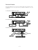
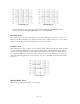
LO MID EQ plot
HI MID EQ plot
Lo Cut Filter Plot
Lo Cut “Out”
Lo Cut “In”