WARNING FOR YOUR PROTECTION, PLEASE READ THE FOLLOWING: The symbols shown above are internationally accepted symbols that warn of potential hazards with electrical products. The lightning flash with arrowpoint in an equilateral triangle means that there are dangerous voltages present within the unit. The exclamation point in an equilateral triangle indicates that it is necessary for the user to refer to the owner’s manual. These symbols warn that there are no user serviceable parts inside the unit.
Digitech VTP-1 Owner’s Manual Table of Contents Introduction.................................................................................1 Warranty ......................................................................................2 Connection Examples ...........................................................3 Rear Panel .................................................................................4 Wiring Scheme ..........................................................................
Introduction Thank you for purchasing the Digitech VTP-1 vacuum tube preamplifier. This product was developed to help you improve the sound of your digital recording, analog recording, and live performance. The VTP-1 offers a better alternative to using the average quality microphone preamps found in the typical multi-input console. For economic reasons, these console preamps are typically of lower quality than a single, dedicated unit.
Warranty 1. The warranty registration card must be mailed within ten days after purchase date to validate the warranty. 2. DigiTech warrants this product, when used solely within the U.S., to be free from defects in materials and workmanship under normal use and service. 3.
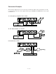
Connection Examples The following diagrams show a few of the ways in which the VTP-1 can be used. Please note that not all digital recorders have direct digital interfacing via AES/EBU and S/PDIF. These may require a translator box.
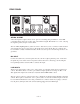
REAR PANEL WIRING SCHEME All of the input and output connectors are “pin 2 hot” meaning that pin number 2 on the XLR connecting cables carries the positive side of the balanced signal. Pin number 3 is “cold”, carrying the negative polarity and pin 1 is the shield. The 1/4” TRS (Tip/Ring/Sleeve) jacks are wired so that when you use 3 conductor cables and balanced signals, the tip is hot, the ring is cold and the sleeve is the shield. The 1/4” jacks can also be used with 2 conductor unbalanced cables.
INSERT LOOP These connectors allow you to insert another processor such as a compressor or de-esser into the signal path. You would insert the processor into this loop to place it in the path leading to the digital output of the VTP-1. Both the SEND and RETURN are balanced TRS jacks with +4 dBu nominal sensitivity. SEND The audio signal produced at the SEND output is taken from a point in the circuit after the VTP1’s tube and EQ stages.
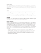
Front Panel POST TRIM Control This control determines the output level presented at the analog and digital outputs. This and the PRE GAIN control work together to allow you to dial in the amount of tube saturation you would like while maintaining a nominal output level. NOTE: The POST TRIM control should generally be set to the fully clockwise position unless you want tube saturation. A reduction in POST TRIM level will reduce the amount of VU meter deflection.
The VU Meter and CLIP LED These two components give you a combined and highly accurate reading of the amount of level at the analog and digital outputs. The VU meter is calibrated in Volume Units which give an average signal level reading. The key word here is “average” because VU meters show the average difference between the peaks and valleys in the level of the program material.
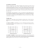
HI MID EQ plot LO MID EQ plot Boosting frequencies adds gain and you may find that this lights the CLIP LED. If this occurs, reduce the level with the PRE GAIN control or POST TRIM. EQ In/Out switch This switch removes the entire EQ circuit from the signal path. This is useful if you want to confirm that your EQ modifications are an improvement on the non-EQ’d signal. If you are not planning on using the EQ, this switch should be left in the “Out” position.
PHASE reversal switch You can invert the phase of the incoming signal. This may be required when you have two mics coming into both channels of the VTP-1 and the distance between the mics is at a critical point where they cause frequency cancellation. Flipping the phase of one of the input channels can overcome the notchy, comb filtering effects caused by multiple mics on a single source. 20 dB PAD switch This inserts a gain reduction circuit into the signal path from the microphone input.
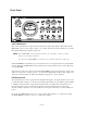
2 Line In (XLR) Line In (1/4" TRS) 2 Mic In (XLR) 3 3 ••• i ••• Clip Monitor 80 Hz Shelving 1 1 Lo Mid Sweep Clip Monitor Hi Mid Sweep Clip Monitor Pre Gain Clip Monitor -1 +235 V Class A Tube Gain Stage Phase Invert EQ In/Out Clip Monitor Optional Input Transformer 12 kHz Shelving Mic/Line Select Clip Monitor Equalizer Pad -20 dB +48V Phantom Power Return Send Post Trim Sample Rate +5 V Format +5 V Clip Monitor Lo Cut Filter Digital Output Transmitter Clip Monitor
VTP-1 SPECIFICATIONS Equivalent Input Noise: Signal-to-Noise Ratio: Total Harmonic Distortion + Noise: Frequency Response: Equalization: Lo-cut Filter: Input Impedance: Output Impedance: Maximum Gain: Maximum Input Level: Nominal Output Level: Maximum Output Level: Digital Output: Power Requirements: Fuse: Lamp bulb: Dimensions: Weight: -127 dBu @ 150Ω > 102 dB, A weighted < 0.
8760 South Sandy Parkway Sandy, Utah, 84070 Telephone (801) 566-8800 FAX (801) 566-7005 International Distribution: 3 Overlook Dr Unit 4 Amherst, New Hampshire 03031 U.S.A. FAX (603) 672-4246 DigiTech™ and VTP-1 are registered trademarks of DOD Electronics Corporation Copyright © 1995 IVL Technologies Ltd. Printed In U.S.A. 6/96 Manufactured in the U.S.A.