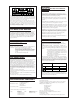
WARNING FOR YOUR PROTECTION, PLEASE READ THE FOLLOWING: The symbols shown above are internationally accepted symbols that warn of potential hazards with electrical products. The lightning flash with arrowpoint in an equilateral triangle means that there are dangerous voltages present within the unit. The exclamation point in an equilateral triangle indicates that it is necessary for the user to refer to the owner’s manual. These symbols warn that there are no user serviceable parts inside the unit.
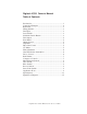
Digitech VCS-1 Owner’s Manual Table of Contents Introduction..........................................................................1 Connection Examples ..........................................................2 Rear Panel ............................................................................3 Wiring Scheme.....................................................................3 Line Input.............................................................................3 Level Switch .....................
Introduction Thank you and congratulations on your purchase of the Digitech VCS-1. This product was developed to give you precise control over dynamics in digital recording, analog recording and live performance. The VCS-1 also has an adjustable-gain vacuum tube stage with analog VU metering and LED peak indication. The compression circuit is comprised of the latest solid state VCA components available.
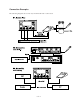
Connection Examples The following diagrams show a few ways in which the VCS-1 can be used.
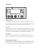
REAR PANEL WIRING SCHEME All of the XLR input and output connectors are pin 2 hot, meaning that pin 2 carries the positive side of the balanced signal. Pin 3 is cold, carrying the negative polarity and pin 1 is the shield. The 1/4” TRS jacks are wired so that when you use 3 conductor cables and balanced signals, the tip is hot, the ring is cold and the sleeve is the shield. The 1/4” jacks can also be used with 2 conductor unbalanced cables. In this case, the tip is hot and the ring and sleeve are grounded.
LINE OUTPUT This output is servo-balanced producing +4 nominal level to XLR and 1/4” TRS connectors. Unbalanced cables may be used also.
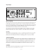
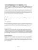
Front Panel OUTPUT CONTROL This center-detented knob controls the output level. The center detent indicates unity gain. Provided, the Tube Gain control is in the center detent position as well. The output level can be adjusted to provide make-up gain when the compressor is active, or reduce the output level fed to a device that will only accept -10 dBV signals. You would also reduce the output level to retain unity levels when increasing the vacuum tube saturation with the TUBE GAIN control.
• Line input level: PROCESS switch set to Bypass, METER switched to Output • Line output level: PROCESS switch set to Active, METER switch set to Output • Compressor gain reduction: PROCESS switch set to Active or Bypass, METER switch set to G.R. • “0 VU” is calibrated to +4 dBu for the input and output VU modes and 0 dB of gain reduction in G.R. mode. VU meters are calibrated in Volume Units to give an average signal level reading.
PEAK LIMITER THRESHOLD The Peak Limiter puts an instantaneous “ceiling” on the transient peak levels of your audio material without affecting dynamics below the threshold. This feature is essential for digital recording and speaker protection for live sound. In the furthest clockwise position, the limiter is off. Turning the control counter-clockwise engages the peak limiter. The LED shows when peak limiting occurs and the VU meter (in the G.R. switch position) will show the amount of attenuation.
METER FUNCTION This switch allows you to toggle the VU meter display between monitoring input level, output level or gain reduction. In the G.R. (gain reduction) setting, the meter needle will center on the 0VU portion of the legend and swing to the left indicating how much attenuation is occurring due to the compressor or peak limiter. When this switch is in the Output position and the channel is active (Process switch is in the Active position), the VU meter will show output level.
APPLICATION NOTES Compression Vocals: Unless the vocalist you are recording has exceptional microphone control, some compression is always welcome on a vocal track. A generally accepted practice, is to use a light compression ratio of 2:1 or so when first recording the vocal to tape then, later to increase the ratio amount depending on the density of the mix. A side effect of vocal compression is that it raises the level of lip smacks, breathing and grunts which may be gated.
Set the Threshold control to the maximum level you want to send to your recorder which, for most digital recorders, is 0 VU. Because 0 VU is referenced differently from one manufacturer to another, start by setting the Limiter Threshold to +10 dBu. For additional protection, you can engage the compressor at 2:1 ratio with a threshold just below the Limiter setting. Gating One of the most basic uses of a gate, is to reduce the noise floor raised by compression.
Creative effects are possible with sidechain gating as well. Sustained sounds from a synthesizer can be layered onto real drums without MIDI using the technique described in the preceding paragraph. Run a synth tone such as noise, or a pure sine wave into the line input of the VCS-1 and out to a mixer channel. Into the sidechain return, run a signal from a snare or bass drum track. This “trigger” track must be well isolated to work properly so use the other channel of the VCS-1 to gate any unwanted sounds.
••• 12 •••
VCS-1 SPECIFICATIONS System Performance Signal-to-Noise Ratio: Total Harmonic Distortion + Noise: Frequency Response: Inputs Connectors: Input Impedance: Maximum Input Level: Outputs Connectors: > 102 dB, A weighted < 0.
Peak Limiter Threshold Range: Attack Time: Release Time: -8 to +24 dBu (off) Typically <10 ms Program dependent Gate: Threshold Range: Maximum Attenuation Attack Time: Release Time: -60 to +20 dBu variable from 0 to 60 dB Typically <10 ms from maximum attenuation Program-dependent De-esser Attenuation Range: Ratio: Detection Filter: 0 (Off) to 28 dB ×:1 3 pole highpass, -3 dB @ 4.
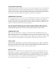
••• 15 ••• DIGITECH VCS-1 SIGNAL FLOW DIAGRAM (One Channel Only)
Printed in the USA 18-2202-A