IN PU T T U TP U O FX PR ES EN C E G U IT AR PR EA M P /S IG N AL PR O C ES SO R -1 8 D -1 2 SP C -6 lip 0 B yp as s Pr og ra m N um be r A Harman International Company S-DISC™ PROCESSING Valve FX Guitar Preamp/ Signal Processor Owner's Manual
Valve FX Owner’s Manual Table Of Contents.............................................................1 Introduction .......................................................................3 Safety Precautions ............................................................3 Lithium Battery Warning....................................................4 Warranty............................................................................4 SECTION 1 - STARTUP Supplying Power ........................................
2 Valve FX Owner’s Manual Modulation Effects ............................................................37 Choruses ....................................................................37 Flangers......................................................................38 Phasers.......................................................................39 Tremolos .....................................................................39 Auto Panners ..............................................................
3 Valve FX Owner’s Manual INTRODUCTION Congratulations, and thank you for your purchase of the DigiTech Valve FX Guitar Preamp / Signal Processor. The Valve FX combines the world’s most powerful digital signal processor, the S-DISC™ with real tube distortion or one of our three most popular solid state distortion types. These digital multi-effects are second to none, and when joined with the warmth and clarity of one of the best analog preamps on the market, the results are amazing.
4 Valve FX Owner’s Manual These symbols warn that there are no user serviceable parts inside the unit. Do not open the unit. Do not attempt to service the unit yourself. Refer all servicing to qualified personnel. Opening the chassis for any reason will void the manufacturer’s warranty. Do not get the unit wet. If liquid is spilled on the unit, shut it off immediately and take it to a dealer for service. Disconnect the equipment during storms to prevent damage. U.K.
Valve FX Owner’s Manual 5 3. DigiTech liability under this warranty is limited to repairing or replacing defective materials that show evidence of defect, provided the product is returned to DigiTech WITH RETURN AUTHORIZATION, where all parts and labor will be covered up to a period of one year. A Return Authorization number may be obtained from DigiTech by telephone. The company shall not be liable for any consequential damage as a result of the product’s use in any circuit or assembly. 4.
6 Valve FX Owner’s Manual SECTION 1 - STARTUP SUPPLYING POWER Line Conditioning - The Valve FX, like any piece of computer hardware, is sensitive to voltage drops, spikes, and surges. Interference such as lightning or power “brownouts” can seriously, and in extreme cases, permanently damage the circuitry inside the unit. Here are some ways to avoid this type of damage: • Spike/Surge Suppressors - This is an inexpensive solution to all but the severest of AC line conditions.
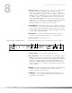
7 Valve FX Owner’s Manual 5) Display Window - The display window shows all current operating and programming information and is comprised of several parts: the LCD display, the input level meter, the Program number indicator, and the Bypass and DSP Clip indicator LEDs. The LCD display shows all Program names, Parameters and Parameter values, and is the communication interface between you and the Valve FX.
8 Valve FX Owner’s Manual 7) Effects Access - This group of buttons allows you to jump directly to the first Parameter of Modules in the currently selected Algorithm. The buttons in this group are: , , , , , , , , and . Also included in this section and sharing buttons with the , , and buttons are the Function keys (indicated by ¡, ™,and £) which act as menu selection keys in the Utility menus.
Valve FX Owner’s Manual 9 5) Outputs - These are the main left and right audio outputs of the Valve FX. Use both outputs when possible since Programs are set up to take advantage of stereo effects. When the Output mode is set to mono, either output can be used. 6) Input - This is the audio input to the Valve FX. Plug your instrument in here. This input is disengaged when the front panel input is used.
10 Section 1 - Startup Valve FX Owner’s Manual
Valve FX Owner’s Manual SECTION 2 - BASIC OPERATIONS 11 MAIN OPERATING MODE After the Valve FX powers-up, the current Program title screen is displayed. This is the main operating mode for the Valve FX from which any of the operating Parameters can be easily reached and modified. PARAMETER ARCHITECTURE The Program’s Parameter architecture in the Valve FX has been designed to be a linear series of items rather than a multiple-level menu (see diagram).
12 Valve FX Owner’s Manual ACCESSING FACTORY PROGRAMS There are four methods for recalling Programs. The first method uses the and Cursor keys. The procedure is as follows: • From the title screen, press the Cursor key. Note that the Program shown in the display changes and the number shown in the LED display increments by one each time the Cursor key is pressed. Pressing the Cursor key causes the reverse to occur: the Valve FX decrements through the Programs in memory.
13 Valve FX Owner’s Manual SECTION 3 - PROGRAMMING USING THE FUNCTION KEYS The Valve FX has three Function keys that perform several functions in different menus. They are located in the bottom row of the Effects Access keys and they share buttons with the , , and options. Each Function key is numbered and performs several functions in the Utility mode (depending on the selected menu screen). These keys are also used in the Program naming process (see Storing / Naming Programs, pg.
14 Valve FX Owner’s Manual THE EFFECTS ACCESS KEYS The Effects s are used to jump to specific places in menus. For example, if a Program contains several delays and you want to change the delay time on only one of them, you could press the Effects Access button from Program’s title screen and you would be jumped to the first Parameter of the first delay in the Algorithm. Press the button again, and you are taken to the first Parameter of the next delay in the Algorithm, and so on.
15 Valve FX Owner’s Manual Program 105 (Infusion) has a Whammy™, a chorus, and a 200 millisecond stereo delay. Let’s suppose that in order to work in your application, it needs to have a 425 millisecond delay. Using this Program as an example for Program modification, the procedure for changing the delay time is as follows: • From the Program title screen, scroll to Program 105 using the and Cursor keys or the Data wheel.
16 Valve FX Owner’s Manual • Press the Cursor key once. The cursor moves to the milliseconds position. • Using the Cursor key, scroll until the last two digits of the delay time read 25. The delay time is now set at .425 seconds. If you change Programs at this point, either through MIDI or via the front panel, any modifications that you have made to the Program will be lost. In order for the Valve FX to remember the changes that you have made, you must store the Program in memory.
17 Valve FX Owner’s Manual • Use the and Cursor keys to select the Algorithm you want to use with the Program. The LED display now shows the Algorithm number as you scroll up or down. • Use the and Cursor keys to begin modifying the Parameters of the currently selected Algorithm to suit your purpose. NOTE: When you change the currently selected Algorithm, the default Parameters selected for the new Algorithm are taken from the first Program in memory that uses it.
18 Valve FX Owner’s Manual functions. The and keys allow you bump an entire name or section of a name either left or right in one-space increments. The procedure is as follows: • In Name mode, use the and Cursor keys to place the cursor underneath the character to be moved. • Press the or keys to move the characters either left or right. The key copies the character under which the cursor sits into memory.
19 Valve FX Owner’s Manual The Store function can also be used to copy Programs from one memory location to another. If no changes have been made to the selected Program and the key is pressed, the Valve FX is placed in Name mode; press the key a second time and the display reads: Copy To Prg ## [PROGRAM NAME] Select the memory location in which you want to place a copy of the selected Program using the / Cursor keys, and press again.
20 Valve FX Owner’s Manual SECTION 4 - EFFECTS AND PARAMETERS ABOUT THE EFFECTS LIBRARY The Effects Library consists of all the effects Modules you can find in the Valve FX. Broken down into individual categories, specific Modules and their abbreviated library names are as follows: Analog Effects Module Name Compressor Distortion Module Abbrv.
Valve FX Owner’s Manual The Distortion Parameters are as follows: 21 Dist On / Bypass ...........Turns the Module on or off. When Modules are turned off, their Parameters disappear from the Parameter menu. To see the Parameters, you must turn the Module on. Distortion Type ..............Selects the type of distortion to be used in the Program. Options are: SATURATED TUBE Hot, loud, and thoroughly modern grind of the best tube amps and guitar rigs.
22 Valve FX Owner’s Manual Equalizers Module Name 10 Band GEQ 4Bnd ParamtrcEQ Cabinet Emulator Module Abbrv. GEQ10 PEQ4 CabEm 4-BAND PEQ / 10-BAND GEQ Description Full bandwidth 10-band graphic equalizer 4-band parametric equalizer w/adjustable Q Full-bore stack sound direct-to-console The equalizer Modules provided in the Valve FX offer superb noise performance, and allow accurate tonal shaping of many different types of sound sources.
Valve FX Owner’s Manual CABINET EMULATOR 23 The Valve FX’s programmable Cabinet Emulator circuitry allows you to use it in both recording and live situations without lugging heavy amps and/or cabinets around. Just connect the Valve FX outputs to a mixing console and kick in the Cabinet Emulator. No miking hassles, no heavy equipment; just a full-on miked cabinet sound.
24 Valve FX Owner’s Manual Reverbs Module Name BigVerb MFX Reverb Gated Reverb BIGVERB / MFX REVERB Module Abbrv. Big MVerb GtRvb Description Studio-quality reverb. Reverb used in multi-effects Algorithms. Professional gated reverb Bigverb is the flagship reverb Module of the Valve FX. It contains 14 Parameters, giving exceptional soundfield and tonal shaping control over reverberation. Bigverb is capable of producing reverberation of virtually any size, shape, depth, timbre or soundfield location.
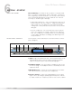
25 INITIAL SOUND AMPLITUDE Valve FX Owner’s Manual EARLY REFLECTIONS SUBSEQUENT REVERBERATIONS TIME EARLY RFLCT PREDELAY RV PRE-DELAY RV SIZE The BigVerb’s ER SPREAD, ER SHAPE and ER DIFFUSION controls allow you to modify the build/decay of the early portion of the reverberation envelope and the relative reverberation time of the midrange reverb frequencies. The ER SHAPE Parameter controls the shape of the early reflection envelope.
26 Valve FX Owner’s Manual Now that we better understand all the aspects and properties of Reverb, the Parameters of the Reverb modules are as follows: Reverb On / Off .............Turns the Module on or off. ER Predelay ..................Controls the length of time before the early reflections are heard. Ranges in milliseconds from 0 to 100. (ER settings in BigVerb only.) ER Spread .....................Controls the length of time over which the early reflections occur.
Valve FX Owner’s Manual 27 RV Predelay ..................Controls the amount of time before the first room reverberations are heard. In an actual acoustic space, the amount of reverberation predelay depends largely on the shape and size of the room and the placement of both listener and sound source within the room. Long RV PREDELAY settings place the reverberation after the program material rather than in sync with it. Ranges in milliseconds from 0 to 100. RV Spread .....................
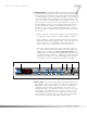
28 Valve FX Owner’s Manual GATED REVERB Gated reverbs usually include adjustable thresholds to set the point at which the reverberations will be gated (cut off). The Valve FX’s RV DECAY TIME control behaves in somewhat the same way, except that instead of setting the length by level (threshold), the length is set by time (in milliseconds). In the left side of the diagram that follows, you can see that reverberations occurring after RVB GATE TIME are muted. This causes the reverb to cut off abruptly.
Valve FX Owner’s Manual 29 Gated reverbs can be found in the library, and their Parameters are as follows: Gated Reverb On / Off..Turns the Module on or off. Reverb Pre-Delay ..........Sets the amount of time before the reverberations are heard. Adjustable from 0 to 100 milliseconds. Rvb Decay Time............Controls the amount of time before the gate cuts off the reverberations. Variable from 20 to 1000 milliseconds. Rvb Envelope ................
30 Valve FX Owner’s Manual Delays/Sampler Module Name Mono Delay x.x 2Tap Delay x.x 4Tap Delay x.x Stereo Delay Modulated Delay Sampler DELAYS Module Abbrv. Dly 2TDly 4TDly SDly ModDly Smpl1.5 Description 1-tap digital delay 2-tap digital delay 4-tap digital delay Stereo digital delay Digital delay with pitch modulation 1.5 second sampler All the delays in this group have the same basic Parameters for controlling the behavior of the Module.
31 Valve FX Owner’s Manual the right of the decimal), you will increase the delay time in increments of 100 milliseconds. Pressing the Cursor key moves the cursor to the third position to the right of the decimal point, or milliseconds position. Each press of the Cursor key from this position increases the delay time in single millisecond steps.
32 SAMPLER Valve FX Owner’s Manual The Valve FX offers a studio-grade sampler Module. It uses a 40 kHz sample rate for great sound quality. Sample recording and playback can be triggered from the external Valve FX switching device, or via MIDI (through continuous controller linkages). Sampling can also be triggered upon detection of a sound source. Parameters of Sampler Modules are as follows: Sampler On / Off ...........Turns the Module on or off. Smpl Plybck Levl...........
Valve FX Owner’s Manual 33 Smpl Triggr Levl............Sets the level at which the audio signal will trigger the sample. Variable from 0 to 100. Smpl Direct Levl............Sets the level of the dry (non-effected) sound. Variable from 1 to 100. Smpl Start Point.............Determines the point at which the sample will begin playing after it has been recorded.
34 Valve FX Owner’s Manual Pitch Shifters Module Name Pitch Shift Mono Detune Dual Detune Whammy Arpeggiator Module Abbrv. Pch Dtn DDtn Wham Arp Description 1-voice pitch shifter Single-voice pitch shifter Mono dual detuner Foot-controlled pitch bending effects Mono arpeggiator The group includes pitch shifters, mono and dual detuners, arpeggiators and DigiTech’s exclusive Whammy™.
Valve FX Owner’s Manual 35 Pitch Shft Amount..........Sets the interval of semitones between the original note and the pitch shifted note. Variable from -24 to +24 (4 octaves). Pitch Detune..................Determines the amount of detuning applied to the shifted note. Variable, in cents, from -100 to +100. Pitch Tracking ...............Controls the sound quality/tracking speed of the pitch shifted material. This control should be set in relation to the Pitch Shift Amount or the interval setting.
36 ARPEGGIATORS Valve FX Owner’s Manual Whammy Pedal .............The WHAMMY PEDAL Parameter reflects the current setting of the continuous control device used to control the whammy effect. This Parameter can be modified manually using the Valve FX’s stand-alone whammy pedal. As the Parameter is modified, the pitch of the original note will change in intervals according to the setting of the WHAMMY FUNCTION. Varies from 0 to 100. Arpeggiator On / Off .....Turns the Module on or off. Arpeggiator Level ....
37 Valve FX Owner’s Manual Mod (Modulation Effects) Module Name Mono Chorus Dual Chorus 4 Phase Chorus Mono Flange Dual Flange Mono Phaser Dual Phaser Mono Tremolo Stereo Tremolo Auto Panner CHORUSES Module Abbrv.
38 Valve FX Owner’s Manual out of the turnaround points. TRIANGLE is a linear chorus effect, and ramps the pitch of the wave up and down with no slowing at turnaround points. LOGARITHMIC and EXPONENTIAL waveforms are more dramatic in their effect on the signal (waveform selection is not available in 4 Phase Chorus).
39 Valve FX Owner’s Manual PHASERS Effect On / Off ...............Turns the Module either on or off. When Modules are turned off, their Parameters disappear from the Parameter menu. To see the Parameters, you must turn the Module on. Phaser Level .................Controls the overall level of the phaser. Variable from 0 to 100. Phaser Regenertn .........Controls the amount of phased sound fed back to the input of the Module. High regeneration settings produce dramatic and interesting unnatural sounds.
40 Valve FX Owner’s Manual Mixers (mono) Mixers (stereo) Mixers (3-out) Module Abbrv. Description Module Abbrv. Description Module Abbrv.
Valve FX Owner’s Manual More Module Name Silencer™ Noise Gate Stereo Ducker Phase Inverter Traditional Wah Automatic Wah NOISE GATES Module Abbrv. NGt SDuc Inv TWah AWah 41 Description Mono noise gate Stereo input / output automatic ducker Inverts signal phase Vintage wah effect Automatic amplitude-based wah effect The Valve FX utilizes Silencer™ digital noise reduction, which can only be found in the S-DISC™, to perform its noise gating chores.
42 Valve FX Owner’s Manual NG Attenuation..............Sets the amount of attenuation (noise floor reduction) when the gate is closed. Varies from 100 dB (below the level of the ungated noise floor) to 0 dB (no attenuation). NG Delay Time..............Allows placement of a slight delay on the source signal after the gate is triggered. This Parameter allows source material with a very fast attack time to be heard in its entirety without the lag in gate response that is common to inferior noise gates.
Valve FX Owner’s Manual 43 Duc Hold Time ..............Controls the amount of time before the ducker disengages after the signal has stopped. Varies from 0.000 to 5.000 seconds. Duc Attenuation ............Adjusts the amount of level attenuation applied to the ducked effects when the ducker is engaged (ducker is engaged when the input level exceeds the setting of CONTROL THRESHOLD). Adjustable from -100 dB to 0 dB. Duc Attack Rate ............
44 Valve FX Owner’s Manual SECTION 5 - THE UTILITY MENU UTILITY MENU The Utility section of the Valve FX contains several functions, including MIDI setup, footswitch setup menu, display contrast, output setting, cabinet emulation mode, sales banner setup, and the factory Program restore menu. These menus are reached by pressing the button. The procedure is as follows: • Press the button once. The display reads: ¡MIDI ™Foot Contrst:4 £Tuner ≥ This is the main Utility options menu.
45 Valve FX Owner’s Manual • Press Function key 1 once. The display reads: ¡MIDI Channel:1 ™Send Prg: Off ≥ Note that a cursor appears under the MIDI Channel number. • Using the / Cursor keys, Function key 1, or the Data wheel select the channel on which you want the Valve FX to receive MIDI data. • To exit, press the button once. SEND PRG (PROGRAM CHANGE) Send Prg determines whether or not corresponding Program Changes will be sent out the Valve FX MIDI port as you select Programs.
46 Valve FX Owner’s Manual devices are set to Disabled, no Program Changes will be sent out the MIDI port. To set up external devices: • From the Program title screen press the button once. The display reads: ¡MIDI ™Foot Contrst:4 £Tuner ≥ • Press Function key 1 once. The display reads: ¡MIDI Channel:1 ™Send Prg: Off ≥ • Press the Cursor key once. The display reads: ¡Prg Send Map ≤™Prg Rcv Map ≥ • Press Function key 1 once.
Valve FX Owner’s Manual 47 • Press the Cursor key once. The display reads: ¡Device # Send ™Prg:1 £As:1 This screen tells you that when the Valve FX sends or receives MIDI Program Change number 1, the selected device will be sent Program Change number 1 on its designated MIDI channel. • Press Function key 2 once. The cursor appears under ™Prg:1. • Using the / Cursor key, select the Valve FX Program number (1-256) that will send the mapped Program Change to the external device.
48 Valve FX Owner’s Manual • Press Function key 2 ( Prg Rcv Map) once. The display reads: ¡Rcv MIDI Prg ™As ValveFX: 1 1 • The cursor appears under Rcv MIDI Prg 1. This display means that MIDI Program Change number 1 is currently set to activate Program number 1 on the Valve FX. • Using the Parameter / Cursor keys, set the Rcv MIDI Prg number to 26. Note that as you change this number, the ™As ValveFX: number changes with it. • Press Function key 2 once.
Valve FX Owner’s Manual 49 • Using the Cursor key, scroll until the display reads: ¡CC Assignments ≤™Disp CC's:Off≥ • Press Function key 1 once. The display reads: ¡LocalCC Link:1 ™Assign • Using the / Cursor keys, select which of the 10 possible CC Links you want to assign to the Parameter. • Press Function key 2 once.
50 Valve FX Owner’s Manual NOTE: The Minimum CC Value and Maximum CC Value Parameters allow you to limit the range of the continuous controllers in the full on and full off positions. The values you select on these two screens determine the behavior of the continuous controller. For example, if a Parameter ranges from 0-100 and Minimum CC Value is set at 40, the lowest the Parameter can be set via continuous control is 40. Likewise, if Maximum CC Value is set at 90, the CC range would run from 40 to 90.
51 Valve FX Owner’s Manual Let’s back up to the LocalCC Link screen for a moment and tackle another scenario: if the Local Link number you want already has a CC assignment, the LocalCC Link display will read: ¡LocalCC Link:1 ™New£[PARAM NAME] This screen gives you the option of either reassigning the link (™New) or selecting a different Local CC Link number along with the Minimum and Maximum CC settings of the current CC Link assignment.
52 Valve FX Owner’s Manual The default CC numbers and how they are used as effect groups on the Valve FX are as follows: CC # 21 22 23 24 25 Function Compression On / Off Distortion On / Off Modulation/Pitch On / Off Delay On / Off Reverb On / Off Control One Patch # 6 7 8 9 0 (10) The Control One foot controller setup is defaulted to use these CC numbers as its CC toggle assignments.
Valve FX Owner’s Manual 53 • Press Function key 1 once. The display reads: Dump MIDI Data? Press ™ for Yes • To dump a copy of the entire contents of the Valve FX memory, press Function key 2. To abort the operation, press . • The display briefly reads: **Dumping MIDI** ** Data ** When the dump is finished, the display returns to: ¡Bulk Dump ≤™Program Dump ≥ • To return to your original position in the Program, press the button.
54 Valve FX Owner’s Manual • Using the / Cursor keys, select the Program number location in which you want the dumped Program to appear. • Press Function key 3 to start the dump. The display briefly reads: * Sending * Program ### * * To abort the operation press the key. MIDI MERGING MIDI Merging allows incoming MIDI data to be merged with any MIDI data generated by the Valve FX before being sent to the MIDI Out port. This is a simple On or Off option.
55 Valve FX Owner’s Manual The submenus included under the Foot Controller setup menu are: Patch Assignment, Continuous Control Pedal, Program List Assignment, and LED Assignment. PATCH ASSIGNMENT The Patch Assignment option allows any Patch in any Bank of the Control One foot controller to recall a Valve FX Program number. To illustrate, let’s set Patch 7 of Bank 4 to recall Program 150 on the Valve FX. The procedure is as follows: • From the Program title screen, press once.
56 Valve FX Owner’s Manual • Finally, use the Cursor keys or the Data wheel to select Program 150. The display should now read: ¡Bank 4 ™Patch 7 ™(PROG.NAME) 150 • Press to exit to your last position in the Program. Now, when you’re in Bank 4, pressing Patch footswitch #7 on the Control One foot controller will recall Program #150 on the Valve FX.
57 Valve FX Owner’s Manual This function is especially useful if you want to use the CC pedal with a Program in more than one way. For example, you can control the level of a Delay linked to CC 4. Then, in real time, reassign the pedal to CC 10 which will control any Parameter in the Program linked to CC 10 (like a Reverb level). LIST UP / DOWN Another special feature of the Foot Controller menu allows you to step through custom sequences of Programs using a single footswitch.
58 CONTINUOUS CONTROL PEDAL Valve FX Owner’s Manual number in the List, press Function key 2 once and use the Data wheel to scroll to the desired Program number. • When you are finished adjusting your List, press the key once to exit to your last position in the Program. This series of menus and submenus allows setup of the continuous controller pedal(s) of the Control One foot controller. Using these pedals, you have real-time control over nearly any Parameter in the Valve FX.
59 Valve FX Owner’s Manual number, or you can change the MIDI channel(s) on which the internal or external pedal will transmit MIDI CC messages to other MIDI devices (using the MIDI Out port). • To change the internal or external CC pedals’ default MIDI CC number, press the appropriate Function key. Note that a cursor appears under the value of the pedal you selected. • Use the Cursor keys or the Data wheel to change the value as desired.
60 Valve FX Owner’s Manual • Press Function key 2. The display reads: ¡Assign Pedal CC ™Calibrate Pedal • Press Function key 1. The display reads: ¡IntPedal:CC 4 ™ExtPedal:CC 16≥ • Press the Cursor key.
61 Valve FX Owner’s Manual • From the Program, press the key once. The display reads: ¡MIDI ™Foot Contrst:4 £Tuner ≥ • Press Function key 2. The display reads: ¡Patches ™CC Ped £PrgList Assign≥ • Press Function key 2 once. The display reads: ¡Assign Pedal CC ™Calibrate Pedal • Press Function key 2.
62 LED ASSIGNMENT Valve FX Owner’s Manual The LED indicators of the Control One foot controller can be set up to function in one of three ways. In the LED Normal mode, the LED above the currently selected Patch will light. In LED Reversed mode, all LEDs on the foot controller except the currently selected Patch are lit. This setting is particularly useful for extreme low light environments where it is impossible to see the actual switches on the foot controller.
63 Valve FX Owner’s Manual • Begin tuning your instrument. As you tune, the note name is shown on the top line of the display, while vertical bars appear on the second line of the display and begin strobing. If the note is sharp, the bars will strobe from left to right. If the note is flat, they’ll strobe from right to left. When the note is in tune, the strobing bars will stop moving and asterisks will appear around the note name on the top line of the display. • To exit the tuner, press .
64 ADJUSTING THE LCD CONTRAST Valve FX Owner’s Manual When you scroll down from 427 Hz, you will also find alternate tunings. Alternate tunings are Ab, G, and Gb. When you use any of the alternate tunings as your reference, tune your instrument so that the display shows normal tuning (E, A, D, G, B, E for guitars) and the Valve FX will do the rest (the display shows normal tuning, but you’ll actually be tuning to your selected reference key).
65 Valve FX Owner’s Manual CABINET EMULATION Each Program in the Valve FX has a local Cabinet Emulation setting that lets you customize each Program’s output sound by choosing from 10 different full-bore guitar stack sounds; 3 warm cabinets, 3 medium cabinets, 3 bright cabinets, and one full-range cabinet for maximum frequency response. The global Cabinet Emulation mode serves as a master on/off control for all Cabinet Emulation effects. The options are: All On, All Off, and Local.
66 Valve FX Owner’s Manual • Press the Cursor key again. The display now reads: ¡Sales:Off ≤™Reinitialize • Press Function key 1 to turn the sales banner on or off. • When you are finished, press the key to exit to your last position in the Program. REINITIALIZING THE VALVE FX This option allows you to restore the contents of the Valve FX’s memory to the original factory condition. WARNING: Performing this function will destroy all user-programmed data.
Valve FX Owner’s Manual followed by Are You Sure? ™Yes £Cancel 67 • This is your last chance to change your mind. To abort the operation, press Function key 3. To restore all Programs to original factory condition, press Function key 2. The display briefly reads: Resetting. Please wait ... after which you will be returned to Program title screen.
68 Valve FX Owner’s Manual SECTION 6 - APPENDIX SPECIFICATIONS A/D Converter: 16 bit PCM D/A Converter: 16 bit PCM Sampling Frequency: 40 kHz DSP Section: Architecture: Static-Dynamic Instruction Set Computer (S-DISC™) Digital Signal Path Width: 24 bits (144.5 dB) Internal Data Path Width: 48 bits (289 dB) Dynamic Delay Memory: 64k x 24 bits (1.68 seconds) Static Delay Memory: 256 24-bit registers (6.55 milliseconds) Data ALU Processing: 10.0 MIPS Address ALU Processing: 15.
69 Valve FX Owner’s Manual FACTORY ALGORITHM DIAGRAMS Following are block diagrams of all the Factory Algorithms. These diagrams show all of the input and output information associated with each Module, as well as the signal path routings for each of the 33 Algorithms.
70 Valve FX Owner’s Manual Algorithm #6 DCho -> 2TDly -> 2 Pans LEFT INPUT Inp 1 DCho Dual Chorus 3x1 Mono 3 x 1 Mixer Cho 1 Cho 2 Out 1 Out 2 Inp 1 Inp 2 Inp 3 Out 1 Inp 1 2TDly 2-Tap Delay 1.
71 Valve FX Owner’s Manual Algorithm #10 Wah -> Wham -> Cho -> Dly TWah Traditional Wah LEFT INPUT Inp 1 Wham Whammy Out 1 Inp 1 Out 1 Inp 1 DCho Dual Chorus Cho 1 Cho 2 3x2 Stereo 3 x 2 Mixer Out 1 Inp 1 In 1 Out L Out 2 Inp 2 In 2 Out R Inp 3 In 3 Out 1 Out 2 SDly Stereo Dly 5 Inp 1 Inp 2 4x2 Stereo 4 x 2 Mixer Out 1 Inp 1 In 1 Out L Out 2 Inp 2 In 2 Out R Inp 3 In 3 Inp 4 In 4 Out 1 Out 2 LEFT MAIN RIGHT MAIN Algorithm #11 Arpeggio2 -> Dly LEFT INPUT Inp 1 Inp 1 Arp Arpeggiator Out 1 Arp
72 Valve FX Owner’s Manual Algorithm #14 Mod Dly -> Revrb MDly Modulation Delay LEFT INPUT Inp 1 2x3 2 x 3 Mixer Out 1 Inp 1 In 1 Inp 2 In 2 Out 1 Out 2 Out 3 Out 1 Out 2 Out 3 Inp 1 4x2 Stereo 4 x 2 Mixer MVRB MFX Reverb Out 1 Inp 1 In 1 Out 2 Inp 2 In 2 Inp 3 In 3 Inp 4 In 4 Out L Out R Out 1 Out 2 LEFT MAIN RIGHT MAIN Algorithm #15 Wham -> 2TDly -> Revrb Wham Whammy LEFT INPUT Inp 1 Out 1 Inp 1 3x1 Mono 3 x 1 Mixer 2TDly 2 Tap Delay 8 Tap 1 Tap 2 Out 1 Out 2 Inp 1 Inp 2 Inp 3 Out 1
Valve FX Owner’s Manual Algorithm #18 DCho -> 4TDly -> Pan 5x1 Mono 5 x 1 Mixer Inp 1 Inp 2 Inp 3 Inp 4 Inp 5 LEFT INPUT Inp 1 DCho Dual Chorus Cho 1 Cho 2 3x3 3 x 3 Mixer Out 1 Inp 1 In 1 Out 1 Out 2 Inp 2 In 2 Out 2 Inp 3 Out 3 In 3 Out 1 Out 2 Out 3 Inp 1 4TDly 4-Tap Delay 1.
74 Valve FX Owner’s Manual Algorithm #20 DFla -> 4TDly -> Pan LEFT INPUT Inp 1 DFla Dual Flange 5x1 Mono 5 x 1 Mixer Inp 1 Inp 2 Inp 3 Inp 4 Inp 5 3x3 3 x 3 Mixer Out 1 Inp 1 In 1 Out 1 Out 2 Inp 2 In 2 Out 2 Inp 3 Out 3 In 3 Out 1 Out 2 Out 3 Inp 1 4TDly 4-Tap Delay 1.
75 Valve FX Owner’s Manual Algorithm #22 Gated Reverb LEFT INPUT Inp 1 GtRvb Gated Reverb Left Right 3x2 Stereo 3 x 2 Mixer Out 1 Inp 1 In 1 Out L Out 2 Inp 2 In 2 Out R Inp 3 In 3 Out 1 Out 2 LEFT MAIN RIGHT MAIN Algorithm #23 4PCho -> 2TDly -> SDuc LEFT INPUT Inp 1 4PCho 4-Phase Chorus Cho 1 Cho 2 Cho 3 Cho 4 5x3 5 x 3 Mixer Out 1 Out 2 Out 3 Out 4 Inp 1 Inp 2 Inp 3 Inp 4 Inp 5 In 1 In 2 In 3 In 4 In 5 Out 1 Out 2 Out 1 Out 2 Out 3 Inp 1 Out 1 Out 2 Out 3 Inp 1 Out 1 Out 2 Out 3 Inp
76 Valve FX Owner’s Manual Algorithm #28 Dly -> Dual Chorus Dly Mono Delay 1.
77 Valve FX Owner’s Manual 5x1 Mono 5 x 1 Mixer Algorithm #32 Pitch -> 4TDly -> Pan LEFT INPUT Inp 1 Pch Mono Pitch Shift Inp 1 Inp 2 Inp 3 Inp 4 Inp 5 2x1 Mono 2 x 1 Mixer Out 1 Inp 1 Inp 2 Out 1 Inp 1 4TDly 4-Tap Delay 1.
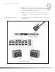
A/D Converter Section 6 - Appendix S-DISC™ Processor (DSP) Compressor D/A Converter Distortion Bypass Switch Output Level Presence Headphone Output 1/4" Output Left 1/4" Output Right Meter BLOCK DIAGRAM Rear Panel Input Front Panel Input 78 Valve FX Owner’s Manual Following is a simplified block diagram of the Valve FX.
79 Valve FX Owner’s Manual FACTORY PROGRAM LIST Top 1 2 3 4 5 6 7 8 9 10 Ten O Solo Mio 6 Voice Chorus Vintage Amp Virtual Wah Soloing 4ths Whammy Deluxe Chorus Hall Synth Pad Swell True Valve Comfort Zone Metal Rock 11 Metal Chor/Verbk 12 Grind Your Axe 13 Behemothk 14 Beat on d’ Brat 15 Step It Up 16 Steamroller 17 H.
80 Function...
8760 South Sandy Parkway Sandy, Utah, 84070 Telephone (801) 566-8800 FAX (801) 566-7005 SO R U International Distribution: 7 Farmington Road Amherst, New Hampshire 03031 U.S.A. FAX (603) 672-4246 R rb ve Re ch Pit 1 lay De d Mo le mp Sa s oru Ch TS C 2 FE x Mi EF DigiTech™, S-DISC™, Whammy™ and Silencer™ are registered trademarks of DOD Electronics Corporation EQ AC S re Mo ES C Copyright © 1994 DOD Electronics Corporation 3 me Na il Ut di/ Mi ss pa By Printed In U.S.A.