A Harman International Company o Ch y 4: Dl v 3: tR b G 2: Rv 1: S-DISC™ PROCESSING Studio 400 4 IN-4 OUT Professional Studio Effects Processor Owner's Manual
IMPORTANT! CAUTION RISK OF ELECTRIC SHOCK DO NOT OPEN A T T E N T I O N : RISQUE DE CHOC ELECTRIQUE - NE PAS OUVRIR W A R N I N G : TO REDUCE THE RISK OF FIRE OR ELECTRIC SHOCK DO NOT EXPOSE THIS EQUIPMENT TO RAIN OR MOISTURE The symbols shown at left are internationally accepted symbols that warn of potential hazards with electrical products. The lightning flash with arrowpoint in an equilateral triangle means that there are dangerous voltages present within the unit.
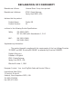
DECLARATION OF CONFORMITY Manufacturer’s Name: Harman Music Group Incorporated Manufacturer’s Address: 8760 S.
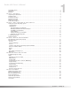
Studio 400 Owner's Manual 1 Table Of Contents . . . . . . . . . . . . . . . . . . . . . . . . . . . . . . . . . . . . . . . . . . . . . . . . . . . . . . . . . . . . . . . . . . . . . . 1 Introduction . . . . . . . . . . . . . . . . . . . . . . . . . . . . . . . . . . . . . . . . . . . . . . . . . . . . . . . . . . . . . . . . . . . . . . . . . . . 2 Warranty . . . . . . . . . . . . . . . . . . . . . . . . . . . . . . . . . . . . . . . . . . . . . . . . . . . . . . . . . . . . . . . . . . . . . . . . . .
Studio 400 Owner's Manual 2 INTRODUCTION Congratulations, and thank you for your purchase of the DigiTech Studio 400. The Studio 400 gives you four completely independent inputs and outputs driven by proven Dual SDISC™ technology. The results are obvious: sparkling clean sound and endless combinations of effects and signal path routings.
Studio 400 Owner's Manual 3 SECTION 1 - SETTING UP UNPACKING THE STUDIO 400 Your Studio 400 was carefully assembled and packaged at the factory. Before you proceed any further, make sure the following items are included: • • • • • (1) (1) (1) (4) (1) Owner's manual DigiTech Studio 400 Studio Effects Processor Power cord Rack screws DigiTech warranty card Please save all packaging materials. They were designed to protect the unit from damage during shipping.
4 Studio 400 Owner's Manual 1d) Information Line - This row of 24 characters (top line of the display) is the Information line. It gives more detailed information about specific functions and items, and contains things like Program names, Parameter names, and Utility or auxiliary information. 1e) Parameter Data Sections - There are four Parameter Data sections in the display. They are immediately below the Information line, and correspond with the <1> through <4> buttons on the front panel.
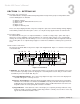
Studio 400 Owner's Manual 5 10) BYPASS - Bypasses all the effects in the Studio 400. 11) DATA WHEEL - The Data Wheel lets you scroll through Programs and change Parameters values. REAR PANEL CONNECTIONS The layout of the Studio 400's simple and straightforward rear panel is illustrated in Figure 1-2. 1 2 3 4 5 6 8 7 Figure 1-2 Rear Panel 1) AUDIO INPUTS - These four XLR or 1/4” balanced inputs can be used for several different combinations of input configurations.
6 Studio 400 Owner's Manual MAKING CONNECTIONS Because of its flexibility, the Studio 400 can be connected in several different ways to meet the requirements of specific applications. The following diagrams offer some ways the Studio 400 can be connected. IN LINE: The Studio 400 can be connected between a line level instrument output (such as keyboards, recording decks, etc.) and a line level input (such as mixing console inputs).
Studio 400 Owner's Manual 7 Figure 1-5 shows an example of a typical stereo effect setup as seen from the console, and shows how to handle both true stereo and mono input signals using two auxiliary sends. This is the method of choice in many recording applications because of the impressive realism and depth of texture that it produces.
8 Studio 400 Owner's Manual From Mixer Aux Send 4 To Mixer Stereo Aux Return 1 (L) From Mixer Aux Send 3 To Mixer Stereo Aux Return 1 (R) From Mixer Aux Send 2 To Mixer Stereo Aux Return 2 (L) From Mixer Aux Send 1 To Mixer Stereo Aux Return 2 (R) Figure 1-6 Quad Mono Input / Dual Stereo Output Configuration Using this method, you could use channel 1 for a long vocal reverb, channel 2 for a short gated snare drum reverb, channel 3 for lead guitar delay, and channel 4 to thicken keyboard instrument
Studio 400 Owner's Manual SECTION 2 - BASIC FUNCTIONS OF THE STUDIO 400 9 GETTING AROUND THE OPERATING SYSTEM The menu structure of the Studio 400 has been specially designed to be easy to use. The display shows the information you need, but to make things even easier for you, illumination in the front panel buttons offers additional operating information. The front panel buttons give you information in one of two ways: 1 - If the button is not lit, its function is INACTIVE.
Studio 400 Owner's Manual 10 to the other. It also gives you several starting places so you can get as close as possible to the custom sound you are trying to create. Once you edit one of the parameters in the FX Module, the default name is replaced with the word "Custom". This means that a default setting has been customized by the user or changed by real-time Modifiers for that program.
Studio 400 Owner's Manual NOTE: Make sure you store any changes you want to save before exiting the edit mode. See pg. 14 for more information. 11 EFFECT & INPUT / OUTPUT CONFIGURATIONS The Studio 400's ability to accommodate a number of different input and output routing configurations makes it an extremely useful and flexible tool for many different applications. Programs 101 through 123 in the Factory Program bank represent all the FX module configurations available in the Studio 400.
Studio 400 Owner's Manual 12 MIDI CCs - When you use MIDI CCs, the Studio 400 responds to CC numbers 0-127 and CHP (channel pressure or aftertouch). This means that you could assign your keyboard's modulation or pitch bend wheel (or any other MIDI CC device) to control effect Parameters. For example, you can have a synth's modulation wheel (usually MIDI CC#1) control the in level of a reverb and chorus in one program while the delay feedback is controlled in another.
Studio 400 Owner's Manual 13 • Press <4> to select the Maximum Value Parameter. • Use the Data wheel to select the maximum Parameter value you want when the controller is in the maximum position. • Press <2> to select the Modifier Type Parameter. • Using the Data wheel to scroll through the Modifier types. Select a MIDI CC number 0 -127 and CHP (Channel Pressure or Aftertouch), L - 1 (LFO1), L - 2 (LFO2), or DYN (Dynamic). NOTE: Make sure you store any changes. See pg.
Studio 400 Owner's Manual 14 COMPARING PROGRAMS During the course of editing Programs, you may find that you want to compare the edited version of the Program to the original, stored version. Fortunately, the Studio 400 provides you with this valuable A/B feature in the Compare function. To compare an edited Program with the original Stored version, do the following: • While the Studio 400 is in program mode, press the button once. The top line of the display reads: *COMPARING ORIGINAL PRG*.
Studio 400 Owner’s Manual SECTION 3 - EFFECTS AND PARAMETERS 15 ABOUT MODULES AND THE EFFECT CHARTS The Studio 400's diverse section of effect Modules allows you to achieve nearly endless combinations of effects and routings. To accomplish that goal, we've supplied you with several different module types in an effects configuration. The processing resources are divided one of four ways per S-Disc. Fig.
16 Studio 400 Owner's Manual DIGITAL AND ANALOG EFFECT LIST Within the Studio 400, lies a vast palette of Digital and Analog effects. All of which are Studio quality. The following is a list of the Effects available: Reverbs, Choruses, Flangers, Phasers, Rotary Speaker Simulator,Tremolo, Auto-Panner, Pitch Shifters, Detuners, Delays (Digital and Analog), Equalizers, Noise Gate, and Compressor.
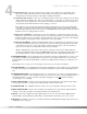
R ev er St b er eo D ua Rev l R er b e St er ver eo b G at Dua ed l St Re Rev er ve e eo rb rb R G oo a m ted Ec R ho ev er b Studio 400 Owner's Manual 17 PARAM. DESCRIPTION Reverbs ✓ ✓ ✓ ✓ ✓ ✓ ✓ FX: Lvl Controls the signal input level fed to the Module. Varies from OFF to 100%. ✓ ✓ ✓ ✓ ✓ ✓ ✓ Dry: Lvl Controls the level of the dry (uneffected) signal. Ranges from OFF to 100%. ✓ ✓ ✓ ✓ ✓ ✓ ✓ Balance Controls the left/right positioning of the dry signal in the stereo soundfield.
Studio 400 Owner's Manual R ev er St b er eo D ua Rev l R er b e St er ver eo b G at Dua ed l St Re Rev . G ve er b r at ed b R oo R m e Ec ver ho b 18 ✓ ✓ ✓ ✓ DESCRIPTION The BLEND control cross-mixes reverberations from the left side into the right side and vice-versa. This can be used to increase the realism of the simulated room by adding reverberations from different parts of the room to each channel. Varies from 0% to 99%.
Studio 400 Owner's Manual 19 CHORUS AND FLANGE Both choruses and flangers use a Low Frequency Oscillator (LFO) to produce their rich, swirling effects. When you change the speed and depth Parameters of modulation effects, you're actually controlling the frequency and amplitude of the LFO. These settings determine the rate and intensity of the modulation effect.
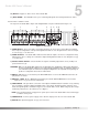
Studio 400 Owner's Manual lF St ua D er la n eo ge Fl an ge 20 PARAM. DESCRIPTION Flangers ✓ ✓ FX: Lvl Controls the signal input level fed to the Module. Varies from OFF to 100%. ✓ ✓ Dry: Lvl Controls the level of the dry (uneffected) signal. Ranges from OFF to 100%. ✓ ✓ Balance Controls the left/right positioning of the dry signal in the stereo soundfield. Varies from -99 (all left) to 99 (all right). ✓ ✓ Speed Controls the Low Frequency Oscillator (LFO) speed of the flanger.
ua lC h St er oru eo s Q ua Dua d l O Ch Cho ct or al us rus C ho ru s Studio 400 Owner's Manual D PARAM. 21 Choruses DESCRIPTION ✓ ✓ ✓ ✓ FX: Lvl Controls the signal input level fed to the Module. Varies from OFF to 100%. ✓ ✓ ✓ ✓ Dry: Lvl Controls the level of the dry (uneffected) signal. Ranges from OFF to 100%. ✓ ✓ ✓ ✓ Balance Controls the left/right positioning of the dry signal in the stereo soundfield. Varies from -99 (all left) to 99 (all right).
Studio 400 Owner's Manual 22 D ua lP St ha er s eo e Ph as e PHASERS Phasers create a copy of the original signal and modulate that new signal’s phase relationship to the original signal. When the two signals are reunited at the output, the modified signal, moving smoothly in and out of phase, causes continuous cancellations and reinforcements at different frequencies throughout the modulating cycle. PARAM. DESCRIPTION Phasers ✓ ✓ FX: Lvl Controls the signal input level fed to the Module.
Studio 400 Owner's Manual 23 ROTARY SPEAKER SIMULAOR / TREMOLO / AUTO PANNER The Rotary Speaker Simluator allows you to emulate the classic rotating speaker sound, without the chiropractic problems that come with moving bulky speaker cabinets. DESCRIPTION ✓ FX: Lvl Controls the signal input level fed to the Module. Varies from OFF to 100%. ✓ Dry: Lvl Controls the level of the dry (uneffected) signal. Ranges from OFF to 100%.
Studio 400 Owner's Manual 24 DETUNERS / PITCH SHIFTERS Detuners are similar to pitch shifters, but the intervals between the detuned signal and the original are much smaller, usually expressed in cents (hundredths of a semitone). The Studio 400 uses percentages of semitones to express the shifted note's distance from the original. For example, with a maximum detune setting of 50%, the pitch is exactly one semitone (50 cents) up from the original.
D ua lP St itc er h eo St Pi er t eo ch Q ua Dua d l O Pit Pitc ct ch h al Sm Pit c oo h H th ar P m itc on h y Studio 400 Owner's Manual 25 PARAM. DESCRIPTION Pitch Shifters ✓ ✓ ✓ ✓ ✓ ✓ ✓ FX: Lvl Controls the signal input level fed to the Module. Varies from OFF to 100%. ✓ ✓ ✓ ✓ ✓ ✓ ✓ Dry: Lvl Controls the level of the dry (uneffected) signal. Ranges from OFF to 100%. ✓ ✓ ✓ ✓ ✓ ✓ ✓ Balance Controls the left/right posistioning of the dry signal in the stereo soundfield.
Studio 400 Owner's Manual 26 on D M ua o D el l D ay el Q ua ay d St De la er eo y St D e er eo lay St D ua er o l A Qu Del na ad ay lo D St g D el er el ay o ay Pr An a e D log el ay De la y DELAYS A delay produces discrete, repeating echoes of the source material at a specified interval. In digital delays, the input signal is "sampled" or recorded into memory, where it is held for the amount of time you specify with the delay time setting, after which the sample is replayed at the output.
Studio 400 Owner's Manual 27 EQUALIZERS The Studio 400 has a broad selection of equalizer Modules to cover virtually any need. Both mono and stereo modules are available. Remember that mono equalizers connected to stereo sources will always sum the stereo signal together for equalization (thus eliminating the stereo image). If you need to maintain the stereo image, use a stereo equalizer module.
Studio 400 Owner's Manual 28 NOISE GATE / COMPRESSOR Noise gates are particularly useful for preventing mic rumble, wind noise, or hum from getting to tape in your recordings, or for gating drum kits to prevent mic bleed. G at e C om pr es so r Compression does exactly what its name implies; it compresses the dynamic range of the signal. It does this by turning signals down as they become louder. After it makes the adjustments, it brings the overall signal back up. PARAM.
Studio 400 Owner's Manual 29 C ho ru Fl s/D an e ge lay /D el ay MULTI EFFECTS MODULES The Studio 400, Multi Effect Modules allow the User to combine either Delay and Chorus or Delay and Flange within one Effect module block. This is ideal for situations where the User needs to add another effect to the Effect Configuration, but is running low on signal processing resources. Within the module, there is a unqiue parameter that allows you route the signal several different ways between the two effects.
Studio 400 Owner's Manual 30 SECTION 4- IN LEVELS & UTILITIES AUTOMATIC AND MANUAL INPUT LEVELING Proper input level adjustment can be the difference between an acceptable recording and a great recording. Fortunately, the Studio 400 has the ability to automatically optimize your input levels based on the signal sent to the input(s). The concept of Auto Leveling is simple: the Studio 400 listens to the signal for about 8 seconds, and sets the input levels accordingly.
Studio 400 Owner's Manual 31 ADJUSTING THE SCREEN CONTRAST The SCRN CONTRAST control in the Utility menu allows you to adjust the contrast of the display from different viewing angles. To change the screen contrast, do the following: • Press . Scroll to Page One of the Utility Menu using the and keys.
Studio 400 Owner's Manual 32 • Press <2> and use the Data wheel to select the MIDI Program change number you want mapped. Note that the number under STUDIOUSER changes along with the MIDI number. • Press <3> and use the Data wheel to select the Studio 400 Program you want the selected MIDI Program change number to recall. As this number increases above Program 100, note that STUDIOUSER changes to STUDIOFACT, indicating that the mapped number will recall the indicated Program number in the Factory bank.
Studio 400 Owner's Manual 33 • Using the Data wheel, select the Program number you want to dump. Note that the AS PRG number changes as you scroll. • Press <3> and use the Data wheel to select the Program location where you want the Program dumped. • To initiate the dump, press <4>. The Information line briefly reads SENDING PROGRAM DUMP... after which it returns to the Program dump screen.
Studio 400 Owner's Manual 34 PROGRAM AUTOLOAD From the factory, the Studio 400 ships with this option turned on. It simply means that any time you change to a new Program, it is automatically loaded into active memory and begins performing its function. When set to off, newly selected Programs must be loaded manually using the button.
Studio 400 Owner's Manual 35 HARMONY TUNING REFERENCE When using Harmony intelligent pitch shifting, the Reference note pitch is set at A=440. If you wish to change the reference note, you can access this function in the Utility menu. Reference can be set from A=427 to A= 453. The procedure is as follows: • Press , scroll to page 7 of the Utility page using the or buttons.
Studio 400 Owner's Manual 36 SECTION 5 - APPENDIX MIDI IMPLEMENTATION CHART Function...
Effect Name Mo d Mo ule T du yp Mo le T e du yp 4th e le Ty - H pe LF Eff ec -F tT UL yp e Studio 400 Owner's Manual GEQ8 GEQ15 GEQ31 St GEQ8 St GEQ15 St PEQ3 PEQ6 St PEQ6 Dual Cho Quad Cho Octal Cho StDual Cho Dual Fla Stereo Fla Dual Pha Stereo Pha RotarySpkr St Tremolo Auto Pan Dual Dtn Quad Dtn Octal Dtn StDual Dtn Smooth Pch Dual Pitch Quad Pitch Octal Pch St Pitch StDual Pch Harmony Delay ✓ ✓ ✓ ✓ ✓ ✓ ✓ ✓ ✓ ✓ ✓ ✓ ✓ ✓ ✓ ✓ ✓ ✓ ✓ ✓ ✓ ✓ ✓ ✓ ✓ ✓ ✓ ✓ ✓ ✓ ✓ ✓ ✓ ✓ ✓ ✓ ✓ ✓ ✓ ✓ ✓ ✓ ✓ ✓ ✓ ✓ ✓ ✓ ✓ ✓ ✓ ✓ ✓ ✓ ✓
Studio 400 Owner's Manual 38 EFFECT CONFIGURATION CHART Configuration 2 Configuration 1 Configuration 3 IN 1 H OUT 1 IN 1 OUT 1 IN 1 IN 2 H OUT 2 IN 2 OUT 2 IN 2 IN 3 H OUT 3 IN 3 OUT 3 IN 3 IN 4 H OUT 4 IN 4 OUT 4 IN 4 Configuration 4 IN 1 H OUT 1 IN 1 H H OUT 2 IN 2 H IN 3 OUT 3 IN 4 OUT 4 H Configuration 7 OUT 2 OUT 3 IN 4 OUT 4 IN 4 OUT 4 IN 3 IN 4 OUT 4 IN 4 F OUT 1 IN 1 IN 2 OUT 2 IN 2 IN 3 OUT 3 IN 3 IN 4 OUT 4 IN 4 H H OUT 1 F Con
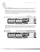
Studio 400 Owner's Manual STUDIO 400 FACTORY PROGRAM LIST 39 CLASSIC REVERBS 1- 1:Rvb 2:GtRv 3:Dly 4:Cho . . . . . . . . . . . . . .Cfg-1 2- Perfect Hall . . . . . . . . . . . . . . . . . . . . . . . . .Cfg-23 3- Stage in a Small Hall . . . . . . . . . . . . . . . . . .Cfg-23 4- Rich Chamber . . . . . . . . . . . . . . . . . . . . . . .Cfg-23 5- Precious Plate . . . . . . . . . . . . . . . . . . . . . . . .Cfg-23 6- Grand Cathedral . . . . . . . . . . . . . . . . . . . . .Cfg-23 7- Large Wood Room . . .
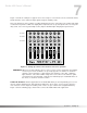
Studio 400 Owner's Manual 40 EFFECT BLOCK CONFIGURATIONS 101) Cfg. 1 (H, H, H, H) 102) Cfg. 2 (H, H, H, H) 103) Cfg. 3 (H, H, H, H) 104) Cfg. 4 (H, H, H, H) 105) Cfg. 5 (H, H, F) 106) Cfg. 6 (H, H, F) 107) Cfg. 7 (H, F, H) 108) Cfg. 8 (F, H, H) 109) Cfg. 9 (F, H, H) 110) Cfg. 10 (F, F) 111) Cfg. 11 (F, F) 112) Cfg. 12 (F) 113) Cfg. 13 (F, H, H) 114) Cfg. 14 (F, H, H) 115) Cfg. 15 (All 1/4) 116) Cfg. 16 (All 1/4) 117) Cfg. 17 (All 1/4) 118) Cfg. 18 (4,4,H,4,4,H) 119) Cfg. 19 (4,H,4,4,H,4) 120) Cfg.
Studio 400 Owner's Manual STUDIO 400 SPECIFICATIONS A/D Converter: 18 bit, 128 x oversampled delta-sigma stereo D/A Converter: 20 bit 64 x oversampled Sampling Frequency: 44.1 kHz 41 DSP Section: Static-Dynamic Instruction Set computer(S-DISC®) Digital Signal Path Width: 24 bits (144.5 dB) Internal Data Path Width: 48 bits (289 dB) Dynamic Delay Memory: 64k x 24 bits (1.4 seconds) Static Delay Memory: 256 24-bit registers (5.8 milliseconds) Data ALU Processing: 11.3 MIPS Address ALU Processing: 16.
Studio 400 Owner’s Manual 42 HARMONY INTERVAL CHARTS Interval Major Minor Harm.Minor Mel.
Studio 400 Owner's Manual USER NOTES....
44 USER NOTES...
8760 South Sandy Parkway Sandy, Utah, 84070 Telephone (801) 566-8800 FAX (801) 566-7005 International Distribution: 3 Overlook Dr Unit 4 Amherst, New Hampshire 03031 U.S.A. FAX (603) 672-4246 DigiTech™, Studio 400, and S-DISC™ are registered trademarks of DOD Electronics Corporation Copyright © 1995 DOD Electronics Corporation Printed In U.S.A. 11/95 Manufactured in the U.S.A.