A Harman International Company S-DISC™ PROCESSING GSP-2101 Artist Studio Tube Preamp / Multi-Effects Processor Owner's Manual
WARNING CAUTION FOR YOUR PROTECTION, PLEASE READ THE FOLLOWING: RISK OF ELECTRIC SHOCK DO NOT OPEN A T T E N T I O N : RISQUE DE CHOC ELECTRIQUE - NE PAS OUVRIR W A R N I N G : TO REDUCE THE RISK OF FIRE OR ELECTRIC SHOCK DO NOT EXPOSE THIS EQUIPMENT TO RAIN OR MOISTURE The symbols shown above are internationally accepted symbols that warn of potential hazards with electrical products.
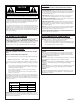
Table of Contents Section 1 - Introduction ..................................................................................................................4 Quick Start...........................................................................................................................4 About the GSP-2101 Artist ................................................................................................5 Packaging ...................................................................................
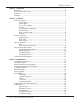
Table of Contents Section 3 - Editing Effects (cont...)..............................................................................................32 [Pitch] FX Library .................................................................................................32 [Gate] FX Library..................................................................................................36 [More] FX Library .................................................................................................
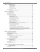
Table of Contents Assigning Programs to Footswitches ....................................................................72 Assigning Parameters to Footswitches/Expression Pedals....................................73 Other Footswitch Functions.................................................................................75 Program Up/Down...................................................................................75 Bank Up/Down........................................................................
Section 1 - Introduction Introduction QUICK START For those of you who prefer to burn now and read later, we've included this Quick Start section to help you do it right the first time. Connect Cables: Connect audio input and output cables to the rear jacks. Balanced (tip-ringsleeve), unbalanced (tip-sleeve) or balanced XLR cables can be used with the output jacks. The rear headphone jack permits you to use the GSP-2101 Artist without an amplifier.
Section 1 - Introduction Introduction ABOUT THE GSP-2101 ARTIST Congratulations, and thank you for your purchase of the DigiTech GSP-2101 Artist Studio Tube Preamp/Multi-Effects Processor. The original GSP 2101 has become the world's most popular professional guitar processor and to prove it, many of the industry's top players have contributed their own presets to the GSP-2101 Artist.
Section 1 - Introduction Introduction WARRANTY 1. The warranty registration card must be mailed within ten days after purchase date to validate this warranty. 2. DigiTech warrants this product, when used solely within the U.S., to be free from defects in materials and workmanship under normal use and service. 3.
Section 2 - The Basics AUDIO CONNECTIONS The Basics Guitar Inputs - The GSP-2101 Artist provides two jacks to choose from when connecting your guitar. One on the front, and one one the back (see diagrams 2-4 & 2-5 ). They are identical except that the front input jack takes priority over the rear input jack (i.e. when you use the front jack, the rear jack becomes inactive).
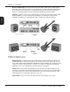
Section 2 - The Basics Mono vs. Stereo Usage - The GSP-2101 Artist can be used in either mono or stereo output applications. When using the 2101 in a mono application, you should set the Output Mode to Mono (found in the Utilities menu). This will ensure that you hear both sides of multi-tap delays, etc. (Please see page 83 for more information regarding Mono/Stereo usage). The Basics Examples - Figures 2-1 and 2-2 show common ways to connect your GSP-2101 Artist to guitar amps and speakers.
Section 2 - The Basics OTHER CONNECTIONS The Basics MIDI - The GSP-2101 Artist is MIDI savvy. Much of the 2101's flexibility can be accessed remotely using MIDI, allowing you to focus more on your playing. The 2101 is complete with the standard MIDI In, Out and Thru jacks on the rear of the unit (see figure 2-5). Connect a MIDI controller (such as a MIDI sequencer, or perhaps a DigiTech MC2 continuous controller pedal) to the MIDI In jack for remote or automated control of the 2101.
Section 2 - The Basics USING FACTORY/USER PROGRAMS The GSP-2101 Artist contains 100 User Programs and 140 Factory Programs. The Factory Programs cannot be copied over, while the User Programs can be copied over. Many of the Factory Programs have been placed in User Program positions for your convenience. The Basics Program Buttons/Data Wheel: The Program [Up/Down] buttons (see fig 2-4) let you select any Program in the 2101 Artist.
Section 2 - The Basics Accessing the Tuner/Tone Generator: The GSP-2101 Artist comes complete with a full-function chromatic tuner and tone generator. To access the tuner, press the [TUNER] button. The display reads: Tuner A = 440 The Basics -- -- -- -- -- -- --- -- -- -- -- -- -As you play a note on the guitar, line two of the display will tell you which note you are playing. The 3rd and 4th lines of the display will begin to show characters moving to the left or to the right.
Section 2 - The Basics FRONT & REAR PANEL DIAGRAMS The Basics Fig 2-4 Fig 2-5 12 GSP-2101 Artist Owner’s Manual
Section 3 - Editing Effects PROGRAMS VS. ALGORITHMS For a Program to function, it must have an Algorithm assignment. In simplest terms, an Algorithm is a group of effects connected together in a specific way. Algorithms tell the GSP2101 Artist which effects to use, while Programs tell the Algorithm how the effects should sound (by setting the parameters to the stored values). Editing Effects An Algorithm contains a group of single-purpose effects called FX Modules (see fig. 3-2).
Section 3 - Editing Effects FX LIBRARY BUTTONS The FX Library buttons (see fig 2-4 on pg. 12) make the GSP-2101 Artist easier and faster to use. These buttons let you jump to the first Parameter page of each Module used in the Program. From there, you can scroll to the Parameter you want using the Parameter [NEXT] and [PREV] buttons.
Section 3 - Editing Effects Suppose you’re using a stereo chorus and that you want to assign Function key [1] to the chorus speed Parameter. The procedure is as follows: • Using the Parameter [NEXT] / [PREV] keys, scroll to CHORUS SPEED. • Press and hold Function key [1] for about two seconds.
Section 3 - Editing Effects NAMING PROGRAMS The GSP-2101 Artist lets you give your Programs and Algorithms custom names (up to 20 characters in length). Use the Data wheel and the Function keys to make naming quick and easy. Function key [1] changes the character from upper to lower case and vice versa. Function key [2] inserts a space into the Program name, and Function key [3] jumps to the numbers in the character set.
Section 3 - Editing Effects STORING CHANGES For modified Programs to be available for later recall, you must store them in memory. To store a Program, do the following: • After you have changed the Program, press the [STORE] button once. The display looks something like this: Editing Effects Save Dry Saturated Tube To: 1 Dry Saturated Tube This screen lets you choose where you want to store the new Program.
Section 3 - Editing Effects ANALOG EFFECTS Every Program has a set of analog effects whose signal routing order is always fixed. These analog effects include Compression, Distortion, and a 7-band Graphic Equalizer. Compression: Every Program in the GSP-2101 Artist has a dynamic range compression circuit specially designed for use with guitars. Compression does exactly what its name implies; it compresses the dynamic range of a signal. It does this by turning signals down as they become louder.
Section 3 - Editing Effects While turning the distortion OFF gives you a clean sound, many guitarists prefer the sound of the tube when it is not overdriven. We call this the Clean Tube setting. It uses the first 12AX7 tube and has one gain control. This clean setting can still be used for very subtle distortion when Gain1 is set very high. Solid State Distortions: The GSP-2101 Artist has three solid-state distortions.
Section 3 - Editing Effects DIGITAL NOISE GATE AND WET/DRY MIXER There are two digital effect modules present in every GSP-2101 Artist Program: The digital noise gate and the wet/dry mixer. The digital noise gate uses DigiTech’s Silencer™ technology, and is used for eliminating excess noise or creating special effects. This module appears in the FX Library when creating your own Algorithms. There may be some unique applications where you want to place a noise gate somewhere else in the effect chain.
Section 3 - Editing Effects Adjustable Q equalizers offer the ability to control the bandwidth of the boost/cut ranges. High Q settings (Q=8) yield extremely narrow bandwidths, where boost and cut have minimal effect on frequencies adjacent to the center frequency. Fig. 3-4 shows how low Q settings affect a wider number of frequencies when the selected band is boost or cut. DigiTech Audio Precision STD AMPL (dBr) vs FREQ (Hz) 20.000 15.000 10.000 Q= 2 Q= 4 Q 0.0 Editing Effects 5.0000 = 8 -5.
Section 3 - Editing Effects [Reverb] FX Library Editing Effects Module Name Multi-FX Reverb BigVerb GigaVerb Gated Reverb Stereo Big Reverb Stereo Gigaverb Stereo Gated Reverb Module Abbrv.
Section 3 - Editing Effects The GigaVerb’s ER SPREAD, ER SHAPE, and RV ROOM SIZE controls let you modify the build/decay of the early portion of the reverberation envelope and the relative reverberation time of the midrange reverb frequencies. Editing Effects Fig. 3-5 The ER SHAPE Parameter controls the shape of the early reflection envelope, and ER SPREAD sets the time over which this early reflection shape is achieved. A chart showing all 16 early reflection shapes can be found on Pg. 24.
Section 3 - Editing Effects -5 dB -10 dB -15 dB -20 dB TIME -5 dB -10 dB -15 dB -20 dB -20 dB -5 dB -3 dB -20 dB -10 dB -15 dB -20 dB -20 dB -11 dB -10 dB -15 dB -20 dB -3 dB -20 dB -8 dB -20 dB 0 dB -10 dB -15 dB -20 dB -20 dB -12 dB TIME -10 dB -15 dB -20 dB -20 dB -14 dB -8 dB -2 dB SHAPE = 13 -10 dB -15 dB -20 dB -15 dB -20 dB 0 dB -5 dB -13 dB 0 dB -5 dB -10 dB -15 dB -20 dB -20 dB -15 dB -10 dB -15 dB -20 dB TIME -2 dB SHAPE = 8 -20 dB 0 dB -5 dB -10 dB -15 dB -20 dB -9
Section 3 - Editing Effects RV Diffusion: RV DIFFUSION controls the smoothness of the reverberation. In a real room, reverberation is naturally diffused by the air. However, diffusion can also be affected by temperature, humidity, and the presence of absorptive or reflective materials in the reverberant space. Ranges from 1 to 10. RV Hi-Freq Decay: Controls the decay length (damping) of the high frequency reverberations. Variable from 25Hz to 20 kHz.
Section 3 - Editing Effects Gated Reverbs - A true gated reverb is simply a reverb followed by a gate. In the GSP-2101 Artist, this combination is emulated in a single Module. Gates usually include adjustable thresholds to set the point at which the reverberations will be gated (cut off). In fig. 3-7,you can see that reverberations occurring at a level below the gate threshold cutoff point are muted.
Section 3 - Editing Effects Rvrb StereoBlend: Appears in stereo Modules only. Controls the amount of reverberation from the left side of the stereo sound field that is heard in the right side (and viceversa). Ranges from 0 to 100. Diffusion: Controls the smoothness of the reverberations. Variable from 1 to 10. LPF Frequency: Sets the frequency below which reverberations will be heard. Adjustable from 25Hz to 20kHz.
Section 3 - Editing Effects Each delay Module has a number that immediately follows the name. These numbers represent the amount of delay time in seconds available to each Module. For example, if the Module name shown in the display reads 4TDLY 0.5, you know that the Module is a 4-tap delay with a maximum of .5 seconds (or 500 milliseconds) of delay time available. The available delay time ranges are 0.5 (500 milliseconds), 1.0 (1000 milliseconds), 2.0 (2000 milliseconds), and 5.0 (5000 milliseconds).
Section 3 - Editing Effects Repeat Hold: This is the infinite repeat Parameter. When turned on, the delay taps will repeat indefinitely until the REPEAT HOLD Parameter is disengaged. See fig. 3-9. -30 dB INITIAL SOUND TIME Fig 3-9 -30 dB TIME Editing Effects AMPLITUDE INITIAL SOUND AMPLITUDE 0 dB 0 dB REPEAT HOLD Fig 3-10 Samplers - The GSP 2101 Artist offers several sampler Modules in different time ranges and input/output routings to maximize flexibility and usefulness.
Section 3 - Editing Effects Playback Level: Determines the overall level of the sample when played back. Variable from 0 to 100. Audio Trigger Mode: Determines whether audio triggering or manual triggering is active. There is one audio triggering option and one manual triggering option. They behave as follows: when set to MAN TR, samples and sampling are triggered using manual methods (footswitch, front panel, etc.).
Section 3 - Editing Effects LFO Speed: Controls the speed of the chorus sweep. The higher this is set, the faster the chorus oscillates back and forth. This will also cause the chorus to modulate deeper (as it goes faster). Variable from 00.06 to 16.00 Hz. LFO Depth: This Parameter sets the sweep depth (intensity) of the chorus. Variable from 0.00 to 40.00 milliseconds.
Section 3 - Editing Effects LFO Waveform Type: Controls the LFO (low-frequency oscillator) waveform pattern of the flange effect. SINE produces a smooth sine wave-type flange with even transitions in and out of the turnaround points. TRIANGLE is a linear chorus effect, and ramps the pitch of the wave up and down with no slowing at turnaround point. LOGTHM or EXPNTL waveforms usually sound best, but don’t be afraid to experiment. See fig.
Section 3 - Editing Effects As a side note, several of these effects are in their second generation of development since the original release of the GSP-2101 (i.e. they have been improved). The smooth pitch shifter and smooth whammy both offer improved tracking capabilities, while the intelligent pitch shifter incorporates new pitch recognition technology. Parameters are as follows: Pitch Shifters Effect On / Off: Turns the Module on or off.
Section 3 - Editing Effects Detuners Effect On / Off: Turns the Module on or off. When the Module is turned off, its Parameters are not displayed and signal will not continue to pass through the module. To see the Parameters, you must turn the Module on. Detuner Level Controls the overall level of the detuner Module. Varies from 0 to 100. Detune (Cents): Controls the amount of detuning applied to the effected sound. Variable, in cents, from -100 to +100.
Section 3 - Editing Effects Whammy™ Effect On / Off: Turns the Module on or off. When the Module is turned off, its Parameters are not displayed, but signal will continue to pass through the module. To see the Parameters, you must turn the Module on. Pedal Down Pitch: Sets the amount of pitch shifting when the pedal is down (the “down” position is when the toe of the pedal is down). Varies from -24 to +24 semitones. This Parameter appears only in the Programmable Whammy.
Section 3 - Editing Effects [Gate] FX Library Module Name S-DISC Silencer St S-D Silencer Noise Gate Stereo Noise Gate Module Abbrv. Shh Shhh NGt SNGt Description Mono S-DISC Silencer™ Noise Reduction Stereo S-DISC Silencer™ Noise Reduction Mono Silencer™ noise gate Stereo Silencer™ noise gate Editing Effects The GSP-2101 Artist is equipped with DigiTech’s Silencer™ technology.
Section 3 - Editing Effects Attack Time: Controls how fast the gate opens after detecting a signal above THRESHOLD. Large numbers yield slower attack times, while small numbers give a fast attack. Varies from 0 to 2000 milliseconds (2 seconds). Release Time: Controls how fast the gate closes after the signal has fallen below HYSTERESIS for the amount of time set by HOLD TIME. Large numbers yield slow release times, while small numbers give a fast release. Varies from 0 to 2000 milliseconds (2 seconds).
Section 3 - Editing Effects [More] FX Library Editing Effects Module Name Mono Tremolo Stereo Tremolo Auto Panner Mono Phaser Dual Phaser Stereo Phaser 4 Voice Phaser 4 Way Auto Panner Phase Inverter Module Name Trm STrm Pan Pha DPha SPha 4PPha 4Pan Inv Description 1-in / 1-out tremolo Stereo input / output tremolo 1-in / 1-out auto panner Mono phaser 1-input / 2-output dual phaser Stereo input/output phaser 1-input/4-output phaser w/4 independent delay times 1-in / 4-out auto panner Inverts signal pha
Section 3 - Editing Effects Another utility module is the Phase Inverter, which simply flips the phase of the signal (great for eliminating acoustic guitar feedback). The last utlity type module in the Fx (MORE) Library is is the Tuning Reference tone generator. This can be very useful when you need to get the whole band in tune (should that be one of your goals). It can also be accessed anytime by simply pressing and holding the [TUNER] button.
Section 3 - Editing Effects LFO Waveform Type: Controls the LFO waveform pattern of the phasing effect. SINE produces a smooth sine wave-type phasing with even transitions in and out of the turnaround points. TRINGL is a linear phasing effect, and ramps the pitch of the wave up and down with no slowing at turnaround points. LOG and EXPN waveforms offer a more intense sound characteristic unique to the GSP-2101 Artist. Wahs Effect On / Off: Turns the Module on or off.
Section 3 - Editing Effects Phase Inverter Phase Inverter Flips the signal phase 180 degrees. Settings are either IN PHASE or OUT OF PHASE. Tuning Reference Level: Controls the output level of the tuning reference tone. Variable from 0 to 100. Editing Effects Reference: Selects the reference tone. This Parameter has settings for standard guitar tuning, standard guitar tuning harmonics (12th fret), E flat guitar tuning tones and 12th fret harmonics, 437-443 Hz tones, and a 1kHz reference tone.
Section 3 - Editing Effects Choruses, delays, reverbs, phasers, flangers, and pitch shifters all rely on a combination of dry and effects signal to produce their characteristic sounds. A good example of this is a chorus. A chorused signal by itself (without a dry signal mixed in) sounds like it’s slowly moving in and out of tune (a dry signal is, of course, just a plain signal). Only when you combine the modulating signal with the dry signal, do you get the dynamic detuning sound you know as a chorus.
Section 3 - Editing Effects Using mixers in the GSP-2101 Artist is especially important because, you may want to turn individual effects on or off using the optional Control One foot controller. If your Algorithm has chorus, delay, and reverb, and you turn off the chorus, you would expect the delay and reverb to stay. Look back at fig. 3-12 and you'll see that if you turn off the chorus, the signal doesn't even get to the delay and reverb. The only signal at the outputs is through the dry Master Mix path.
Section 3 - Editing Effects • Overload indicator - Indicates (when lit) that the digital section of the GSP-2101 Artist is being overloaded. If this indicator lights when the GSP-2101 Artist is receiving signal, simply reduce the overall level of the digital effects in the Program. Again, let your ears be the judge. If the indicator lights regularly and no undesirable distortion is present, it can be ignored.
Section 4 - Algorithm Usage SELECTING ALGORITHMS The Algorithm you choose for a Program determines the basic function of the Program, so make sure you choose an Algorithm that has all the Modules you want to use in an appropriate configuration.
Section 4 - Algorithm Usage • Use the FX Library keys to select the Module you want to hear. The display shows the current Module being auditioned, and the test message. It will look something like this: **** **** Sound Test **** **** MVrb: Multi-FX Reverb • To select another Module from the same group (e.g. Gigaverb, Bigverb, and MFX reverbs are all in the [REVERB] library), press the same library button until the Module you want to hear is shown in the display.
Section 4 - Algorithm Usage IMPORTANT: When you start building your own Algorithms, remember that CPU and RAM block counts are approximate. It is normal to run out of blocks even your math says you have a few blocks still available. Also, every Algorithm automatically requires about 28 CPU blocks for the master mix control and miscellaneous input and output routing. This gives you about 228 CPU blocks to work with (484 CPU blocks on a PPC-210 equipped GSP-2101 Artist).
Section 4 - Algorithm Usage Algorithm Construction Hints: Building an Algorithm is much like having a large rack full of individual effects and patching them all together with dozens of patch cables. We have found that if you don't prepare for this task, it can be a little overwhelming. Use the following hints to make this task much easier. • Study the Factory Algorithms - We have mentioned this in other sections of this manual, but it can never be said too often.
Section 4 - Algorithm Usage • Pressing the [ENTER] button once. The Edit LED lights and the display reads: Entering edit mode, Please wait / followed by: Edit Algorithm: ¡Modify Current Alg ™Create New Alg £Exit Edit Mode You can now select whether you want to modify the current Algorithm, create a new Algorithm, or Exit directly out of Edit mode. Algorithm Use Edit LED indicator - This LED is located in the Display Window (see pg. 12) and indicates (when lit) that you are in Algorithm Edit mode.
Section 4 - Algorithm Usage To add effects Modules to an Algorithm, you must first enter Edit mode. Edit mode is reached by scrolling to the Algorithm screen (one screen to the right of the Title Screen) and pressing the [ENTER] or [ADD] button. IMPORTANT: Do not confuse Edit mode with the mode in which Parameter values are modi fied. The term “Edit mode” is used only when referring to Algorithm editing. Changing Parameter values is called “Program modification”.
Section 4 - Algorithm Usage • Continue adding Modules by selecting the Module and pressing [ENTER]. If there is not enough memory for the Module, the display will tell you that the Module won't fit. Deleting Individual FX Modules: The [DELETE] key allows you to delete a single Module from an Algorithm, to delete all the Modules from within an Algorithm, or to delete an entire Algorithm from memory. When deleting Modules or Algorithms, you are bound by the same conditions as those for adding Modules.
Section 4 - Algorithm Usage • To delete the selected Module from the Algorithm, press [ENTER]. The display briefly reads: ** Module Deleted ** ** Successfully ** after which the display reads: Select effect to DEL And Then Press Enter Link When Done ¡Show Alg £Exit • To delete another Module, repeat this process. Deleting All FX Modules: It is also possible to delete all the existing Modules from the Algorithm without deleting the entire Algorithm.
Section 4 - Algorithm Usage • Press the [DELETE] key. The display reads: Delete Algorithm: Yes ¡ No ™ Edit £ • To delete the Algorithm from memory, press Function key [1]. The display briefly reads: Progs using Alg will be lost, You Sure ? Yes No ¡ ™ • To delete the Algorithm from memory, press Function key [1]. The display briefly reads: **** **** Algorithm Use **** DELETING **** ALGORITHM after which you’ll be returned to the current Program. To abort the command, press Function key [2].
Section 4 - Algorithm Usage • Use the [NEXT] and [PREV] keys to select the Module you want to Move. • Press Function key [1] to "pick up" the Module. Note that the MOVE on the display is replaced by DROP and that the Module name disappears from the menu. • Use the [NEXT] and [PREV] keys to select the location where you want the Module. • Press Function key [1] to drop the Module into place in front of the selected Module.
Section 4 - Algorithm Usage Linking (Audio Path Routing) After you have added all the Modules that you want to use, the next step is to connect the inputs and outputs of each Module to the other Modules or to the GSP-2101 Artist inputs and outputs. The linking process itself is similar to connecting patch cables between discrete effects devices; that is, you are connecting outputs to inputs. There are four conditions that govern the capabilities of the Link mode.
Section 4 - Algorithm Usage Now let’s add the modules to a new Algorithm. Because we are using several effects at one time, managing the wet/dry relationship can be a little tricky. By handling it in DSP land, we can make each of the effects as wet or dry as we want. The master Wet to Dry mixer found in every program works globally with the effects used in a Program. • Select a Program where you want this Algorithm to be used (remember after it is created, it can be used in several Programs).
Section 4 - Algorithm Usage • Press [1] for yes.The display should look like this: Link FX OUTs to INs Press Store when rdy Left Input To MVrb INP 1 ≥ AutoLink has made a guess as to how we may want to link our FX Modules together. But, by using the the [NEXT] and [PREV] buttons we notice that not everything is right according to our original diagram. Drawing the AutoLink’s work, looks like this: Input MFX Rvrb St.
Section 4 - Algorithm Usage • After linking all the FX Modules correctly, press the [STORE] button. After renaming our new Algorithm (optional), press [STORE] again to compile the Algorithm into something we can use. The new Algorithm is now loaded in the currently selected Program. Check to make sure that the master Wet to Dry mixer is set to All Wet. After you tweak up the effect’s parameters (to get the sound just right), use the [STORE] button to save your new sound.
Section 4 - Algorithm Usage The Algorithm is now saved in memory for use with Programs. When you exit, the GSP-2101 Artist selects the newly saved Algorithm for use in the Program that you return to. “Why can’t I copy over an existing Algorithm?” The GSP-2101 Artist keeps track of where Algorithms are used. Since Algorithms can be used in various Programs, things can become a little confusing if you’re not careful.
Section 4 - Algorithm Usage Edit Algorithm: ¡Modify Current Alg ™Create New Alg £Exit Edit Mode • Press Function key [1]. The display reads: Number of S-DISCs: ¡Single Alg ™Single -> Dual £Exit Edit Mode • Press Function key [2]. The Algorithm is converted, after which the display reads: Select effect to ADD And Then Press Enter Link When Done ¡Show Alg £Exit Algorithm Use The Algorithm has been successfully converted to dual S-DISC, giving you twice as much space for effects.
Section 4 - Algorithm Usage • Press Function key [2]. The Algorithm is converted, after which the display reads: Select effect to ADD And Then Press Enter Link When Done ¡Show Alg £Exit The Algorithm has been successfully converted to dual S-DISC, giving you twice as much space for effects. Adding/Deleting Effects Modules in Dual S-DISC Algorithms (PPC-210 Users Only): The procedure for adding/deleting effects Modules to dual S-DISC Algorithms is identical in many respects to the conventional method.
Section 4 - Algorithm Usage You can continue to add/delete Modules as described above until both S-DISCs are out of memory and / or processing blocks. NOTE: If you find that you’re still running out of room, try adding your Modules in a different order. Sometimes it’s possible to fit more Modules in an Algorithm just by changing the screen order. Remember that the order of the Modules on the screen doesn’t really matter (except when using AutoLink™) because you can manually Link any output to any input.
Section 5 - The GSP-2101 and MIDI MAIN MIDI RECEIVE CHANNEL The GSP-2101 Artist MIDI Channel Parameter allows you to select the MIDI channel on which the GSP-2101 Artist will receive MIDI data. This can be set to channels 1 - 16, ALL, or NONE. If this Parameter is set to ALL, MIDI data received on any MIDI channel will be recognized. If it is set to NONE, the GSP-2101 Artist will not recognize incoming MIDI data.
Section 5 - The GSP-2101 and MIDI • Press Function key [3]. The cursor moves to AS GSP PRG. • Change the number to 131 using the Data wheel. When you’re finished, press [MIDI] to exit. Now, when the GSP-2101 Artist receives Program Change number 26 via MIDI, Program 131 will be recalled. Any number of Program Changes (up to the MIDI maximum of 128) can be mapped to recall any GSP-2101 Artist Program.
Section 5 - The GSP-2101 and MIDI • With the cursor still under the DEVICE number, use the Data wheel to select the MIDI channel you want the device to respond to (if this Parameter is set to DISABLED, the GSP-2101 Artist will not send out any Program Change messages for that device). • Press Function key [2]. The cursor appears under the GSP PROGRAM number on the second line of the display.
Section 5 - The GSP-2101 and MIDI • Using the Data wheel, select the CC number you want to control the Parameter with. The display looks something like this: ¡Link:2 ™Min/Max SCho Level Links to MIDI CC 7 £Delete Link ≤ ≥ • After you have selected a CC number, set the min/max value by pressing function button [2]. The display looks something like this: ¡SCho Level Links to MIDI CC 7 ™Min Value 0 £Max Value 100 Note the Min/Max settings that allow you to scale Parameter ranges to fit your personal taste.
Section 5 - The GSP-2101 and MIDI DISPLAY ACTIVE LINKED PARAMETER This is a simple option that allows you to see the CC values change in real time. When this Parameter is set to YES, the CC response time is slower, making it useful for troubleshooting MIDI CC problems (for quickest response time, this Parameter should be set to NO). Also, when this item is set to YES, any CC activity will cause the GSP-2101 Artist to automatically jump to the Parameter screen of the value being controlled.
Section 5 - The GSP-2101 and MIDI • Press Function key [2]. The display reads: Press ¡ to start MIDI data dump of entire system. 18340 Bytes Total The total number of bytes to be dumped may vary depending on how many of your own custom Programs and Algorithms you have in memory. • To dump the data, press Function key [1]. The display briefly reads: *** Sending MIDI *** System Data *** / *** 18340 Bytes *** *** *** *** after which you are returned to the MIDI setup menu.
Section 5 - The GSP-2101 and MIDI MIDI MERGING The MIDI merging option allows incoming MIDI data to be merged with any MIDI data generated by the GSP-2101 Artist before being sent to the MIDI Out port. To change the setting of the MIDI merging option, do the following: • After entering the MIDI setup menu, press the [NEXT] key four times. The display reads: ¡MIDI merging Off ™Send Front Panel program change? No ≤ ≥ • To change the MIDI merging setting, press Function key [1].
Section 6 - The GSP-2101 and the Control One CONFIGURING THE PEDALBOARD The optional Control One foot controller can help you get the most out of your GSP-2101 Artist. Since the Control One talks to the 2101 using a proprietary communication protocol, it offers better response time and capabilities not available with convention MIDI pedalboard controllers. The Control One includes 12 footswitches for Program and Parameter control. It also features a built-in Expression Pedal.
Section 6 - The GSP-2101 and the Control One • Press Function key [2] once. The display reads: ¡Patch Assignment ™LED Assignment £Exp Pedals and CC Xmit Setup ≥ • Press Function key [3]. The display reads: ¡Exp ™Exp £Exp and Pedal Calibrate Pedal Min/Max Pedal CC Assign CC Xmit Setup • Press Function key [1].
Section 6 - The GSP-2101 and the Control One BANKS/PATCHES The Control One helps you organize your sounds into ten groups called Banks. Each of these Banks contain ten patches which are user programmable to do one of several functions.
Section 6 - The GSP-2101 and the Control One • Simply press one of the ten Patch footswitches to Link that Program to that switch. If you choose a footswitch that is already assigned to do something else besides select a Program, the display reads: Do you want to re-assign this foot switch ? ¡Yes ™No Pressing the [1] function button re-assigns the function of the footswitch while pressing [2] will leave everything as it was, aborting the procedure.
Section 6 - The GSP-2101 and the Control One • Press one of the ten Patch footswitches or move the Expression pedal to Link that Parameter. If you choose a footswitch that is already assigned to do something else (besides select a Program), the display will read: Do you want to re-assign this foot switch ? ¡Yes ™No Pressing Function button [1] re-assign the function of the footswitch, while pressing [2] leaves everything as it was, aborting the procedure. Press Yes.
Section 6 - The GSP-2101 and the Control One ¡Link:2 ™Min/Max MVol MVol Links to Int Exp Pedal £Delete Link ≤ ≥ NOTE: Remember that the 2101 recalls the stored value first and pays no attention to Parameter links. If you want a Program to load with a Master Volume of 3, store it with Master Volume set at 3. Setting the link at Min Value doesn’t mean that the Program automatically loads with that Min Value loaded. • Press one of the ten Patch footswitches or move the Expression pedal to Link that Parameter.
Section 6 - The GSP-2101 and the Control One Int. Exp pedal CC: The Expression pedal of the Control One can also send MIDI CC data . This switch function allows you to re-assign the MIDI CC assignment for the Expression pedal (i.e. if the pedal were assigned to send CC4 data, it could be temporarily re-assigned to send CC7 using the Int. pedal CC function). The procedure for setting up a footswitch function is as follows: • Press the [UTILITY] key once.
Section 6 - The GSP-2101 and the Control One • Press the [UTILITY] key once. The display reads: ¡Output Mode: Stereo ™Foot Controller ≥ • Press Function key [2] once. The display reads: ¡Patch Assignment ™LED Assignment £Exp Pedals and CC Xmit Setup ≥ • Press Function key [3]. The display reads: ¡Exp ™Exp £Exp and Pedal Calibrate Pedal Min/Max Pedal CC Assign CC Xmit Setup • Press Function key [3].
Section 6 - The GSP-2101 and the Control One • Press the [UTILITY] key once. The display reads: ¡Output Mode: Stereo ™Foot Controller ≥ • Press Function key [2] once. The display reads: ¡Patch Assignment ™LED Assignment £Exp Pedals and CC Xmit Setup ≥ • Press Function key [3]. The display reads: ¡Exp ™Exp £Exp and Pedal Calibrate Pedal Min/Max Pedal CC Assign CC Xmit Setup • Press Function key [3].
Section 6 - The GSP-2101 and the Control One • Press the [UTILITY] key once. The display reads: ¡Output Mode: Stereo ™Foot Controller ≥ • Press Function key [2] once. The display reads: ¡Patch Assignment ™LED Assignment £Exp Pedals and CC Xmit Setup • Press Function key [3]. The display reads: ¡Exp ™Exp £Exp and Pedal Calibrate Pedal Min/Max Pedal CC Assign CC Xmit Setup • Press Function key [2].
Section 6 - The GSP-2101 and the Control One OTHER PEDALBOARD TIDBITS Here are a few other features that you will want to learn about to get the most out of your Control One foot controller. Programming Set Lists: Another special feature of the Control One allows you to step through custom sequences of Programs using a single footswitch. This sequence is called a List. It can be up to 31 steps in length, and each step has its own Program number assignment.
Section 6 - The GSP-2101 and the Control One LED Assignments: The LED indicators of the Control One can be set up to function in one of three ways. In the LED NORMAL mode, the LED above the currently selected Patch will light. In LED REVERSED mode, all LEDs on the pedalboard except the currently selected Patch are lit. This setting is particularly useful for extreme low light environments where it is impossible to see the actual switches on the pedalboard.
Section 6 - The GSP-2101 and the Control One Alternate Bank Up/Down Footswitches: Many players feel that giving up two footswitches for use as Bank Up/Down switches in every Bank is just too costly. So, the GSP-2101 Artist allows you to re-assign the Program/Bank/Tuner and Bypass footswitches as Bank Up/Down footswitches. To change this assignment, do the following: • Enter the Utilities menus by pressing the [UTILITY] button once.
Section 7 - Other Utilities MONO VS. STEREO OUTPUT MODES To get the best results from your GSP-2101 Artist, the output mode must be set for your particular setup. The OUTPUT MODE option in the Utility setup menu allows you to set whether the unit will be operated in stereo (dual outputs) or mono (single output).
Section 7 - Other Utilities FACTORY RESET Factory Reset gives you two different options for restoring the memory of the GSP-2101 Artist to its original factory condition. The first (RELOAD PRG/ALG) is a hard reset that permanently erases all user Programs and Algorithms in the unit. If you want to erase everything you’ve programmed, this is the reset to use. The second option (RESET Utility/MIDI) is a softer reset that simply restarts the GSP-2101 Artist.
Section 7 - Other Utilities • After entering Utility mode, press [NEXT] once. The display reads: ¡Global EQ ™Factory Reset ≤ • Press Function key [2]. The display reads: ¡Reload Prg/Alg ™Reset Utility/MIDI • Press Function key [2] once. The display reads: Resetting Please wait ... / after which you will be returned to the current Program.
Section 7 - Other Utilities The following diagram shows exactly what happens during the course of a seamless Program change. The example settings are: HOLD TIME = 1.4 seconds; RAMP TIME = 2.6 seconds. 40 dB Original Program New Program Decaying (no signal) HOLD TIME = 1.4 seconds RAMP TIME = 2.
Section 7 - Other Utilities Note that a cursor appears under the 0 in HOLD TIME. This is the seamless Program change setup menu. This menu is Program specific; each Program can be set up to behave differently using this setup screen. IMPORTANT: The seamless Program change setup menu only shows up WHEN THE CUR RENTLY LOADED PROGRAM USES A SINGLE S-DISC ALGORITHM. If this menu does not appear using the procedure described above, check to make sure that the Program uses a single S-DISC Algorithm.
Section 8- Advanced Applications STUDIO HINTS The GSP-2101 has two sets of outputs that do slightly different things. Both the XLR and 1/4” outputs provide great sounding audio signals, but the XLRs can also have the Cabinet Emulation enabled (see pg. 20). Having both sets of outputs at your disposal can make things a little easier for you in the studio. Most mixing consoles have input channels that accept both XLR inputs and 1/4” line inputs.
Section 8- Advanced Applications Now we are actually feeding the two pre-amps the same guitar signal. Most Amp heads have an FX loop, so lets put this to work for us. Use an instrument cable to connect the Amp head’s FX loop out to the Left (mono) FX Loop return of the 2101. Take another cable and connect the 2101’s Left Output (mono) to the Amp head’s FX loop return.
Section 9 - Appendix SPECIAL CHARACTERS There are several special characters that the GSP-2101 Artist uses to tell you at a glance exactly what is happening. Most special characters in the GSP-2101 Artist are in reversed type, that is, reversed out of a black background, and they usually appear in the upper right-hand corner of the display. There are instances, however, when they appear somewhere other than in the upper righthand corner or when more than one special character appears in the display.
Section 9 - Appendix Int. Lydian Aug. Int. üOct C ü7th B ü6th A üOct ü#5th G# ü#4th F# ü3rd Major Pent. Int. Minor Pent. Int. Blues Int. Whole Tone Int. Hlf-Whl Dim. Int. Whl-Hlf Dim.
Section 9 - Appendix Appendix EQUALIZERS 6-Band Graphic 10-Band Graphic 15-Band Graphic Low-Pass Filter High-Pass Filter 1-Band Parametric 3-Band Parametric 5-Band Parametric Band-Pass Filter Notch Filter Cabinet Emulator REVERBS MFX Reverb BigVerb GigaVerb Gated Reverb Stereo BigVerb Stereo GigaVerb Stereo Gated Reverb DELAYS Mono Delay 0.5 Mono Delay 1.0 Mono Delay 2.0 Mono Delay 5.0 Stereo Delay 0.5 Stereo Delay 1.0 Stereo Delay 2.0 2-Tap Delay 0.5 2-Tap Delay 1.0 2-Tap Delay 2.0 2-Tap Delay 5.
Section 9 - Appendix Factory Algorithm Routing Diagrams Following are block diagrams of all the Factory Algorithms. These diagrams show all of the input and output information associated with each Module, as well as the signal path routings for each of the 32 Algorithms. Algorithm #1 CabEm>DCho Dly Rvb Cabinet Emulator LEFT INPUT Dly 2 Mono Delay 2.
Section 9 - Appendix Algorithm #6 Cho>2TDly>StTrem LEFT INPUT Inp 1 PEQ3 3-Band Parametric Out 1 Inp 1 DCho Dual Chorus Cho 1 Cho 2 3x2 Stereo 3 x 2 Mixer Out 1 Inp 1 In 1 Out L Out 2 Inp 2 In 2 Out R Inp 3 In 3 Out 1 Out 2 Inp 1 2TDly 2-Tap Delay 5.
Section 9 - Appendix Algorithm #11 St Pch>Dly>Revrb LEFT INPUT RIGHT INPUT Inp 1 Inp 2 SPch Stereo Pitch Shift 4x2 Stereo 4 x 2 Mixer Out 1 Inp 1 In 1 Out 2 Inp 2 In 2 Inp 3 In 3 Inp 4 In 4 A Out L Out R SDly 2 Stereo Dly 2.
Section 9 - Appendix Algorithm #15 2TDly>2 Reverbs 2x1 Mono 2 x 1 Mixer LEFT INPUT RIGHT INPUT Inp 1 Inp 2 Out 1 Inp 1 PEQ3 3-Band Parametric Out 1 Inp 1 2TDly2 2 Tap Delay 2.
Section 9 - Appendix Algorithm #20 Pha>Cho>2Tap>Pan Pha Mono Phaser LEFT INPUT Inp 1 2x1 Mono 2 x 1 Mixer Out 1 Inp 1 Inp 2 Out 1 Inp 1 DCho Dual Chorus 3x1 Mono 3 x 1 Mixer Cho 1 Cho 2 Out 1 Out 2 Out 1 Inp 1 Inp 2 Inp 3 Inp 1 5x2 Stereo 5 x 2 Mixer 2TDly 2-Tap Delay 5.
Section 9 - Appendix Algorithm #23 Mod Dly>St Revrb MDly Modulation Delay LEFT INPUT Inp 1 2x2 Stereo 2 x 2 Mixer Out 1 Inp 1 In 1 Out L Inp 2 In 2 Out R SBIG Stereo Big Rvb Out 1 Out 2 4x2 Stereo 4 x 2 Mixer Out 1 Inp 1 In 1 Out L Out 2 Inp 2 In 2 Out R Inp 3 In 3 Inp 4 In 4 Inp 1 Inp 2 Out 1 Out 2 LEFT MAIN RIGHT MAIN Algorithm #24 Whammy>2Tap>Rvrb Wham Whammy LEFT INPUT Inp 1 Out 1 Inp 1 2TDly2 2 Tap Delay 2.
Section 9 - Appendix Algorithm #28 Dly>Ducked Revrb Dly 2 Mono Delay 2.0 LEFT INPUT Inp 1 2x1 Mono 2 x 1 Mixer Out 1 Inp 1 Inp 2 Out 1 Inp 1 SDuc Stereo Ducker BIG Big Verb Out 1 Inp 1 Out 2 Inp 2 Inp 3 Out 1 Out 2 3x2 Stereo 3 x 2 Mixer Inp 1 In 1 Inp 2 In 2 Inp 3 In 3 Out L Out R Out 1 Out 2 LEFT MAIN RIGHT MAIN Algorithm #29 No Digital LEFT INPUT RIGHT INPUT LEFT OUT RIGHT OUT Algorithm #34 Wham2>4 Tap Dly LEFT INPUT Inp 1 Whm2 Smooth Whammy 4TDly2 4 Tap Delay 2.
Section 9 - Appendix PPC-210 users only:PPC-210 Algorithms These Algorithms are only available in PPC-210-equipped GSP-2101 Artists running version 2.00.
Section 9 - Appendix Factory Program List Lead On Me . . . . . . . . . . . . . . F9 Smiling Chords. . . . . . . . . . . . F9 Sonofa Blues Solo . . . . . . . . . . F9 Studio Strat. . . . . . . . . . . . . . . F7 Band Of Jeeps.. . . . . . . . . . . .F13 Airgulls. . . . . . . . . . . . . . . . . . .F3 Mount Shasta . . . . . . . . . . . . F21 Wetness. . . . . . . . . . . . . . . . . . F7 MyNervousPhase . . . . . . . . . . F9 Wild Wild Wah Wes. . . . . . . F25 Cuccurullo Lead. . . . . . . . . . .
Section 9 - Appendix Appendix 157 158 159 160 161 162 163 164 165 166 167 168 169 170 171 172 173 174 175 176 177 178 179 180 181 182 183 184 185 186 187 188 189 190 191 192 193 194 195 196 197 198 199 200 201 202 203 204 205 206 207 208 209 210 211 212 213 214 215 216 217 218 219 220 221 222 223 224 225 226 227 228 229 230 231 232 233 234 235 102 Black Hole . . . . . . . . . . . . . . F19 Chicken Pickin’. . . . . . . . . . .F25 Parallel Chor&Dtn . . . . . . . . . F3 Lotus Lead. . . . . . . . . . . . .
FX Loop Return Left Appendix GSP-2101 Artist Owner’s Manual FX Loop Return Right Rear Panel Input Front Panel Input FX Loop Send FX Loop Bypass, Summed, No Sum Compressor A/D Converter Meter S_DISC™ Processor (DSP) Gain 1 Distortion D/A Converter Output Level Analog Graphic EQ Cabinet Emulator Cabinet Emulator Headphone Output Cabinet Emulator Switch 1/4" Output Left 1/4" Output Right Master Volume VCA Balanced XLR Output Right 1 2 3 1 2 3 Balanced XLR Output Left Section 9 - App
Section 9 - Appendix Function...
Section 9 - Appendix Specifications Digital Conversions: A/D Converter . . . . . . . . . . . . 18 bit, 128 x oversampled delta-sigma stereo D/A Converter . . . . . . . . . . . . 18 bit PCM Sampling Frequency . . . . . . . . 48 kHz DSP Section: Architecture . . . . . . . . . . . . . . Static/Dynamic Instruction Set Computer (S-DISC™) Digital Signal Path Width . . . 24 bits (144.5 dB) Internal Data Path Width. . . . 48 bits (289 dB) Dynamic Delay Memory . . . . . 256k x 24 bits (5.
Section 9 - Appendix Appendix Active Speaker Compensator 7,12 Algorithms 13,45-62, 95-99 creating 46 deleting 51,52 linking 55,56 modifying 49-51 naming 16, selecting 45 Alternate Set Up Configurations 88 Audio Block Diagram 103 Appendix 92-108 Bypass 10,82 Cables 4 Cabinet Emulator 7,20 Chorus 30,31 Compression 18 Continous Control 66-68,78-80 Control One 4,9,71 banks 73,76,83,104 calibration 71,72 expression pedal 71-75,77,78 functions 74,76,77 patches 73 set lists 81 CPU Blocks 46,47,90,91 Delay 27,28
Section 9 - Appendix Silencer 36,37 Special Characters 90 Specifications 105 Test Button 45 Tone Generator 10,11 Tremolo 38,39 Tuner, Chromatic 10,11,81 Tuning Reference 38,41 Utilities 83-89 Waranty 6 Wah 38,40 automatic 38 smooth 38 traditional 38 Appendix GSP-2101 Artist Owner’s Manual 107
8760 South Sandy Parkway Sandy, Utah, 84070 Telephone (801) 566-8800 FAX (801) 566-7005 InterNet: www.digitech.com International Distribution: 3 Overlook Drive, Unit 4 Amherst, New Hampshire 03031 U.S.A. FAX (603) 672-4246 DigiTech™, S-DISC™, Whammy™, AutoLink™ and Silencer™ are registered trademarks of DOD Electronics Corporation Copyright © 1996 DOD Electronics Corporation Printed In U.S.A. 4/96 Manufactured in the U.S.A. GSP-2101 Artist Part No. 18-0267-F OS V3.