
Owner`s manual


3–12 SF72 Storage Enclosure Operation
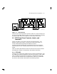
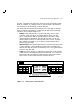
3.2.2 Drive DC Power Switches
Four drive dc power switches are on the lower front side of the SF72
storage enclosure. Each drive dc power switch is associated with a disk
ISE position, as shown in Figure 3–5.
An indicator in each drive dc power switch illuminates to show that
nominal power is being applied to the associated disk ISE. The switches
are shown on the icon located on the front of the chassis of the SF72
enclosure.
Setting a drive dc power switch connects power to the associated disk ISE
and causes the disk ISE to spin up and run a self-test. After setting the
drive dc power switch, you must press the Ready button on the OCP to
bring the disk ISE on-line.
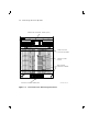
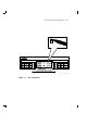
3.3 SF72 Rear Panel Controls and Indicators
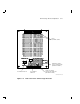
Figure 3–8 shows the rear panel of the SF72 storage enclosure. The DSSI
connectors are on the top rear side of the enclosure. The ac power switch,
line voltage selector switch, and power supply fault indicator are on the
bottom rear of the enclosure, on the power supply chassis, as shown in
Figure 3–8. These controls and indicators affect operation of the entire
SF72 enclosure.
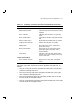
Table 3–4 summarizes the functions of the rear panel controls and
indicators. Details are provided in the paragraphs that follow.
Table 3–4 Summary of SF72 Rear Panel Control/Indicator Functions
Control/Indicator Function
Power Supply Chassis
AC power switch Applies line voltage to dc power supply.
Line voltage
selector switch
Selects between 120 Vac (60 Hz) and 240
Vac (50 Hz) line voltage.
Power supply
fault indicator
Illuminates for fault or overtemperature
in enclosure.