
Owner`s manual


SF72 Storage Enclosure Operation 3–11
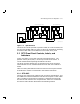
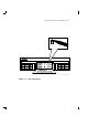
The four 7-segment LED displays on the front of the OCP display these
DSSI ID numbers. If a display is not lit, then that disk ISE position in
the enclosure is not occupied by an RF72 disk ISE.
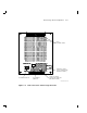
The three disk ISE controls and indicators are to the right or left side
of the 7-segment LED displays. These controls, with their associated
indicators, are as follows (Figure 3–7):
• Ready—The Ready button is a push-to-set switch with a green
indicator. When pressed in, the Ready button causes the disk
ISE to come on-line. After the Ready button is pressed, it takes
approximately 60 seconds for the disk ISE to come on-line. The
green indicator remains lit while the disk ISE is on-line. However,
this indicator may blink or go out entirely when the disk ISE is
performing heavy seeks.
• Write Protect—The Write Protect button is a push-to-set switch with
a yellow indicator. When the Write Protect button is engaged, the
data on that disk ISE cannot be overwritten, nor can any new data be
written to that disk ISE.
• Fault—The Fault button is a momentary switch with a red indicator.
A disk ISE fault is indicated when the red indicator is lit. Press the
Fault button once to display the disk ISE fault code, and a second
time to clear the fault code and clear the disk ISE fault.
Write
Protect
Ready Fault
DSSI
ID
Write
Protect
Ready Fault
DSSI
ID
d
igi
t
al
SHR_X1128_89
1
2
Figure 3–7 SF72 Controls and Indicators