
Owner`s manual


3–8 SF72 Storage Enclosure Operation
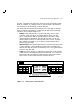
Colored labels on the inside of the door on the OCP help identify each
of the DSSI buses. In a single-host configuration, colors represent the
following:
• Blue represents DSSI bus 1.
• Red represents DSSI bus 2.
• Yellow represents DSSI bus 3.
• Green represents DSSI bus 4.
In a dual-host configuration, colors represent the following:
• Blue represents DSSI bus 1.
• Red represents DSSI bus 2.
• Yellow represents DSSI bus 3.
• Green represents DSSI bus 4.
• Blue/white represents DSSI bus 5.
• Red/white represents DSSI bus 6.
Refer to the inside cover of the SF Family Label Booklet for further
details.
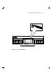
The two indicators behind the OCP door are TERM PWR (termination
power, top) and SPLIT (bus mode, bottom). The TERM PWR indicator
lights green whenever the SF72 storage enclosure is connected to a
DSSI bus. The SPLIT indicator lights green only when the enclosure is
operating in split-bus mode, as described in Section 3.1.2.
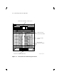
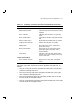
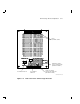
Four switchpacks (Figure 3–6), one for each of the four disk ISEs, are
located to the right and left of the two indicators behind the OCP door.
The switch to the left is the MSCP enable switch and is in the down
position when MSCP is enabled. The other switches are used to set the
DSSI ID number, where the rightmost switch is the least significant.
Switch settings are shown in Tables 3–2 and 3–3.