
Owner`s manual


SF72 Storage Enclosure Operation 3–7
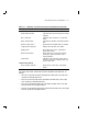
Table 3–1 Summary of SF72 Front Panel Control/Indicator Functions
Control/Indicator Function
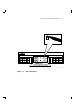
Operator Control Panel
TERM PWR indicator Indicates when termination power is being
supplied.
SPLIT indicator Indicates when enclosure is in split-bus
mode.
MSCP enable switch (Leftmost bit) Enables or disables the disk
ISE.
DSSI ID select switch (Rightmost bit) Enables DSSI ID number.
7-segment LED displays Display disk ISE DSSI ID number.
Ready button Brings disk ISE on-line. (LED lights
green when ready.)
Write Protect button Places disk ISE in write-protect mode.
(LED lights yellow when disk ISE is
write-protected.)
Fault button Indicates a disk ISE fault (when LED is
lit RED). Press once to display fault code,
twice to clear fault.
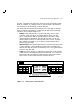
Lower Front of SF72
Drive dc power switches Apply power to disk ISEs; show power
status.
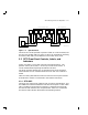
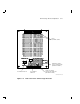
The icons on the door located on the OCP represent each disk ISE, as
follows:
• The icon in the top left front represents the disk ISE in the left rear
of the SF72 storage enclosure.
• The icon in the top right front represents the disk ISE in the right
rear of the SF72 storage enclosure.
• The icon in the bottom left front represents the disk ISE in the left
front of the SF72 storage enclosure.
• The icon in the bottom right front represents the disk ISE in the right
front of the SF72 storage enclosure.