
Owner`s manual


SF72 Storage Enclosure Operation 3–5
TAPE
ISE
0
HOST
SYSTEM 1
KFMSA
7
DISK
ISE
1
DISK
ISE
2
DISK
ISE
3
DISK
ISE
4
TTM
DSSI BUS 0
SF72-JK (THROUGH-BUS)
SF72-JK (SPLIT-BUS)
TTM
DISK
ISE
5
DISK
ISE
6
SHR-X0111-90
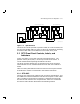
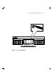
Figure 3–4 Split-Bus Mode
The SF72–HK variant operates in split-bus mode, in a similar fashion, but
only the rear two disk ISEs are used. An SF72–UK upgrade kit consisting
of two RF72 disk ISEs can be added to an SF72–HK at any time.
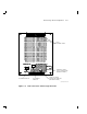
3.2 SF72 Front Panel Controls, Labels, and
Indicators
Figure 3–5 shows a front view of the SF72 storage enclosure. The
operator control panel (OCP) is on the top front of the enclosure. It
can be accessed without opening the cabinet front door.
The drive dc power switches are on the bottom front of the enclosure.
These switches are not accessible when the front door of the cabinet is
closed.
Table 3–1 briefly describes the functions of the SF72 front panel controls
and indicators. Details are contained in the sections that follow.
3.2.1 SF72 OCP
The SF72 OCP contains four identical sets of controls and indicators, and
two additional indicators behind the front door of the panel. Unless a disk
ISE is installed in the enclosure and power is applied to that disk ISE,
the controls and indicators are non-operational. Table 3–1 summarizes
the controls and indicators discussed in the following sections.