
Owner`s manual

3–4 SF72 Storage Enclosure Operation
TAPE
ISE
0
HOST
SYSTEM 1
KFMSA
7
DISK
ISE
1
DISK
ISE
2
DISK
ISE
3
DISK
ISE
4
TTM
DSSI BUS 0
SF72-JK (THROUGH-BUS)
SHR-X0110-90
DSSI
TERMINATOR
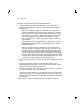
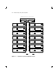
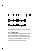
Figure 3–3 Through-Bus Mode
The SF72–HK variant operates in through-bus mode, in a similar fashion,
but only the rear two disk ISEs are used. An SF72–UK upgrade kit
consisting of two RF72 disk ISEs can be added to an SF72–HK at any
time.
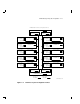
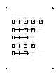
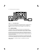
3.1.2 Split-Bus Mode
In split-bus mode, two disk ISEs in the SF72–JK storage enclosure
operate on or are part of two separate DSSI buses. The DSSI bus enters
the enclosure from the rear, at the leftmost or rightmost DSSI connector.
The DSSI bus for the left half of the enclosure is connected to the left rear
disk ISE (facing the front of the enclosure), then the left front disk ISE,
and finally terminated at the transition termination module (TTM) for the
left half of the enclosure.
The DSSI bus for the right half of the enclosure is connected to the right
rear disk ISE (facing the front of the enclosure), then the right front disk
ISE, and finally terminated at the TTM for the right half of the enclosure.
Refer to Figure 3–4. Split-bus mode is not supported in dual-host
configurations.