
Owner`s manual

SF72 Storage Enclosure Operation 3–3
SYS
A
108-inch
BC21Q-09
70-inch
SF200 I/O
PORT
Magazine
Subsystem
Storage
Enclosure
Tape
SYS
A
SF200 I/O
PORT
Magazine
Subsystem
Tape
SYS
A
SF200 I/O
PORT
T
T
D D
SF72
108-inch
BC21Q-09
108-inch
BC21Q-09
70-inch
70-inch
42-inch
BC21Q-3F
BC21R-5L
BC21R-5L
BC21R-5L
D D
SF200 I/O
PORT
70-inch
SYS
BC21R-5L
108-inch
BC21Q-09
70-inch
BC21R-5L
SF200 I/O
PORT
SYS
108-inch
BC21Q-09
70-inch
BC21R-5L
SF200 I/O
PORT
SYS
108-inch
BC21Q-09
B
B
B
Storage
Enclosure
SF72
D D
D D
SHR-X0168-90
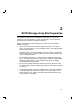
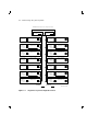
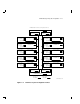
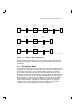
Figure 3–2 Dual-Host Bus Configurations
Either of these variants operate in one of two bus modes. These modes
are called through-bus and split-bus, and are described in the sections
that follow.
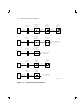
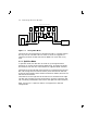
3.1.1 Through-Bus Mode
In through-bus mode, all four disk ISEs in the SF72–JK storage enclosure
operate on or are part of the same DSSI bus. The DSSI bus enters the
enclosure from the rear, at the rightmost DSSI connector. The DSSI
bus is then connected to the left rear disk ISE (facing the front of the
enclosure), then the left front disk ISE, onto the right front disk ISE, then
the right rear disk ISE, and finally out the leftmost (facing rear again)
DSSI connector. At this point, the DSSI bus is either terminated (with
a DSSI terminator, part number 12–31281–01), connected to another
SF72 storage enclosure (operating in split-bus mode in a single-host
configuration), or connected to the array I/O panel and onto another
system (in a dual-host configuration). Refer to Figure 3–3.