SF72 Storage Enclosure and SF200 Storage Array Owner’s Manual Order Number EK–SF72S–OM–001 Digital Equipment Corporation
First Edition, January 1991 The information in this document is subject to change without notice and should not be construed as a commitment by Digital Equipment Corporation. Digital Equipment Corporation assumes no responsibility for any errors that may appear in this document. Restricted Rights: Use, duplication, or disclosure by the U. S. Government is subject to restrictions as set forth in subparagraph ( c ) ( 1 ) ( ii ) of the Rights in Technical Data and Computer Software clause at DFARS 252.
Contents About This Manual 1 v Introduction 1.1 1.2 1.3 SF200 Storage Array Overview . . . . . . . . . . . . . . . . . . . . . . . SF72 Storage Enclosure Overview . . . . . . . . . . . . . . . . . . . . . Related Documentation . . . . . . . . . . . . . . . . . . . . . . . . . . . . . 2 SF200 Storage Array Site Preparation 3 SF72 Storage Enclosure Operation 3.1 3.1.1 3.1.2 3.2 3.2.1 3.2.2 3.3 3.4 3.5 3.6 SF72 Configurations . . . . . . . . . . . . . . . . . . . . . . . Through-Bus Mode . . . . . .
iv Contents 4 4.1 4.2 Troubleshooting Verifying a Hardware Problem . . . . . . . . . . . . . . . . . . . . . . . . Recovering from a Disk ISE Fault Condition . . . . . . . . . . . . . 4–1 4–5 Glossary Index Figures 1–1 1–2 2–1 2–2 3–1 3–2 3–3 3–4 3–5 3–6 3–7 3–8 4–1 4–2 Front View of the SF200 Storage Array . . . SF72 Storage Enclosure . . . . . . . . . . . . . . . Single-Host System Configuration Sheet . . Dual-Host System Configuration Sheet . . . Single-Host Bus Configurations . . . . . . . . .
About This Manual This manual is intended for users of the SF200 storage array and SF72 storage enclosure. This manual will provide users with all the information they need to operate these devices in a safe and effective manner. The information in this manual is organized as follows: • Chapter 1, Introduction, contains a product description and specifications for the SF200 storage array and SF72 storage enclosure.
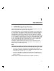
1 Introduction 1.1 SF200 Storage Array Overview The SF200 storage array is a storage rack cabinet designed to hold SF72 storage enclosures and magazine tape subsystems. The SF200 storage array is intended to be installed in one or both sides of a host system. All operator control panels (OCPs) project through the front door of the storage array to allow easy access.
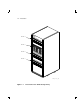
1–2 Introduction SF LEVEL 4 20 0 LEVEL 3 0 1 2 3 0 4 1 5 2 6 3 LEVEL 2 4 5 6 LEVEL 1 SHR_X1101_89 Figure 1–1 Front View of the SF200 Storage Array
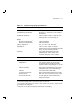
Introduction 1–3 Table 1–1 SF200 Storage Array Specifications Characteristic Specification Number of disk ISEs Minimum: 2, maximum: 24 Formatted storage capacity Minimum: 2, maximum: 24 (in 2 GByte increments) Dimensions (nominal) 152.4 cm (60.5 inches) H, 60.96 cm (24.0 inches) W, 76.2 cm (34.0 inches) D Weight Minimum configuration1 Maximum configuration2 179.62 kg (396 lb) 442.25 kg (975 lb) Agency compliance FCC, UL, IEC, CSA, and VDE Temperature +10°C to +40°C (+50°F to +104°F). Derate 1.
1–4 Introduction Table 1–1 (Cont.) SF200 Storage Array Specifications Characteristic Specification Recommended Environmental Limits3 Nonoperating environment Temperature -40°C to +66°C (-40°F to +151°F) Relative humidity 10% to 80%, noncondensing Altitude 4900 meters (16,000 feet) SF200 acoustic noise 6.8 bells Nominal airflow through enclosure 360 to 520 cubic feet/minute Input power requirements (47 to 63 Hz normal operation) 6.00 A (per phase) @ 100 to 120 Vac (60 Hz), 3.
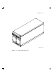
Introduction 1–5 SHR_X1123C_89 Figure 1–2 SF72 Storage Enclosure
1–6 Introduction The SF72 storage enclosure has the following features: • The SF72 storage enclosure can operate in one of two modes: through-bus (described in Section 3.1.1) or split-bus (described in Section 3.1.2). – When in through-bus mode, all of the disk ISEs connect to a single common DSSI bus inside the SF72 enclosure.
Introduction 1–7 Table 1–2 SF72 Storage Enclosure Specifications Characteristic Specification Number of disk ISE positions 4 (RF72 disk ISEs) Formatted storage capacity SF72–HK1 2 GBytes 2 SF72–JK 4 GBytes Dimensions (nominal) 26.7 cm (10.5 inches) H, 22.2 cm (8.75 inches) W, 71.1 cm (28.0 inches) D Weight (nominal) SF72–HK1 34.93 kg (72 lb) 2 SF72–JK 41.28 kg (91 lb) Agency compliance FCC, UL, IEC, CSA, and VDE Temperature +10°C to +40°C (+50°F to +104°F). Derate 1.
1–8 Introduction Table 1–2 (Cont.) SF72 Storage Enclosure Specifications Characteristic Specification Recommended Environmental Limits3 Nonoperating environment Temperature -40°C to +66°C (-40°F to +151°F) Relative humidity 10% to 80%, noncondensing Altitude 4900 meters (16,000 feet) SF72 enclosure acoustic noise 6.2 bells Nominal airflow through enclosure 45 to 65 cubic feet/minute Input power requirements (47 to 63 Hz normal operation) 2.70 A @ 100 to 120 Vac (60 Hz), 1.
2 SF200 Storage Array Site Preparation The SF200 storage array is intended for installation in a Class A computer room environment. It must be operated in an environment that meets the conditions specified in Table 1–1. Before installing the SF200 storage array, make sure the following conditions are met: • The SF200 storage array requires 3-phase ac power. Each phase draws up to 6 amperes in a fully configured array, and produces 6400 BTUs of heat per hour.
2–2 SF200 Storage Array Site Preparation KFMSA/DSSI Single-host Configuration Sheet KFMSA XMI Node # Bus 1 DSSI ID # Device Type DSSI ID # Node Name ALLO_CLASS SF200 Box # System ID Device Type DSSI ID # Node Name ALLO_CLASS SF200 Box # ALLO_CLASS SF200 Box # ALLO_CLASS SF200 Box # ALLO_CLASS SF200 Box # Device Type DSSI ID # Node Name ALLO_CLASS SF200 Box # Device Type DSSI ID # Node Name ALLO_CLASS SF200 Box # Device Type DSSI ID # Node Name ALLO_CLASS SF200 Box # System ID ALLO_CLASS SF
SF200 Storage Array Site Preparation 2–3 KFMSA/DSSI Dual-host Configuration Sheet KFMSA XMI Node # Bus 1 DSSI ID # Device Type DSSI ID # Node Name Bus 2 DSSI ID # ALLO_CLASS SF200 Box # Device Type DSSI ID # Node Name System ID Device Type DSSI ID # Node Name System ID ALLO_CLASS SF200 Box # Device Type DSSI ID # Node Name System ID Device Type DSSI ID # Node Name ALLO_CLASS SF200 Box # Device Type DSSI ID # Node Name ALLO_CLASS SF200 Box # System ID ALLO_CLASS SF200 Box # Device Type DSS
3 SF72 Storage Enclosure Operation This chapter contains the following information: • A description of the various bus modes and system configurations in which the SF72 storage enclosure functions • A description of all front and rear panel controls and indicators • Instructions on how to power up the SF72 storage enclosure • Instructions on how to bring the SF72 storage enclosure on- and off-line 3.
3–2 SF72 Storage Enclosure Operation Magazine SF72 SF200 I/O Tape PORT Subsystem Storage Enclosure SYS 108-inch 70-inch A BC21Q-09 BC21R-5L D T Magazine Tape Subsystem T D 42-inch BC21Q-3F PORT D D 42-inch SF200 I/O SF72 Storage Enclosure D D BC21Q-3F SplitBus SF72 Storage Enclosure SYS 108-inch 70-inch 42-inch A BC21Q-09 BC21R-5L BC21Q-3F D D D D DSSI TERMINATOR 12-31281-01 Magazine SF200 I/O Tape PORT Subsystem T SYS 108-inch 70-inch A BC21Q-09 BC21R-5L
SF72 Storage Enclosure Operation 3–3 SF200 I/O Magazine Tape PORT Subsystem SYS 108-inch 70-inch A BC21Q-09 BC21R-5L T SF72 SF200 I/O Storage Enclosure D D D D 42-inch BC21Q-3F SF200 I/O Magazine Tape SF200 I/O PORT Subsystem PORT PORT 70-inch 108-inch SYS BC21R-5L BC21Q-09 B T SYS 108-inch 70-inch 70-inch 108-inch SYS A BC21Q-09 BC21R-5L BC21R-5L BC21Q-09 B SF72 SF200 I/O SF200 I/O Storage Enclosure PORT SYS 108-inch 70-inch A BC21Q-09 BC21R-5L D D D
3–4 SF72 Storage Enclosure Operation SF72-JK (THROUGH-BUS) TAPE ISE 0 DISK ISE 1 DISK ISE 2 HOST SYSTEM 1 DISK ISE 3 DISK ISE 4 TTM KFMSA 7 DSSI BUS 0 DSSI TERMINATOR SHR-X0110-90 Figure 3–3 Through-Bus Mode The SF72–HK variant operates in through-bus mode, in a similar fashion, but only the rear two disk ISEs are used. An SF72–UK upgrade kit consisting of two RF72 disk ISEs can be added to an SF72–HK at any time. 3.1.
SF72 Storage Enclosure Operation 3–5 SF72-JK (THROUGH-BUS) TAPE ISE 0 DISK ISE 1 HOST SYSTEM 1 DISK ISE 2 DISK ISE 3 SF72-JK (SPLIT-BUS) DISK ISE 4 DISK ISE 5 DISK ISE 6 TTM TTM KFMSA 7 DSSI BUS 0 SHR-X0111-90 Figure 3–4 Split-Bus Mode The SF72–HK variant operates in split-bus mode, in a similar fashion, but only the rear two disk ISEs are used. An SF72–UK upgrade kit consisting of two RF72 disk ISEs can be added to an SF72–HK at any time. 3.
3–6 SF72 Storage Enclosure Operation OPERATOR CONTROL PANEL (OCP) digi tal Write Ready Protect Fault DSSI ID DSSI ID Write Ready Protect Fault FRONT COVER CAPTIVE SCREWS FRONT COVER DOOR ENCLOSURE CAPTIVE SCREWS DRIVE DC POWER SWITCHES Figure 3–5 Front View of the SF72 Storage Enclosure SHR-X0126A-90
SF72 Storage Enclosure Operation 3–7 Table 3–1 Summary of SF72 Front Panel Control/Indicator Functions Control/Indicator Function Operator Control Panel TERM PWR indicator Indicates when termination power is being supplied. SPLIT indicator Indicates when enclosure is in split-bus mode. MSCP enable switch (Leftmost bit) Enables or disables the disk ISE. DSSI ID select switch (Rightmost bit) Enables DSSI ID number. 7-segment LED displays Display disk ISE DSSI ID number.
3–8 SF72 Storage Enclosure Operation Colored labels on the inside of the door on the OCP help identify each of the DSSI buses. In a single-host configuration, colors represent the following: • Blue represents DSSI bus 1. • Red represents DSSI bus 2. • Yellow represents DSSI bus 3. • Green represents DSSI bus 4. In a dual-host configuration, colors represent the following: • Blue represents DSSI bus 1. • Red represents DSSI bus 2. • Yellow represents DSSI bus 3. • Green represents DSSI bus 4.
SF72 Storage Enclosure Operation 3–9 digi tal Write Ready Protect Fault DSSI ID 1 DSSI ID Write Ready Protect Fault 2 SHR_X1128B_89 Figure 3–6 SF72 Switchpacks
3–10 SF72 Storage Enclosure Operation Table 3–2 DSSI ID Switch Settings (Single-Host) Disk ISE Positions 1, 2, 4, and 7 Setting 1 Left Rear (LR) Left Front (LF) Right Front (RF) Right Rear (RR) 001 010 011 100 Positions 3 and 8 Left Rear (LR) Left Front (LF) Right Front (RF) Right Rear (RR) 1 ‘‘0’’ 101 110 110 101 = down, ‘‘1’’ = up.
SF72 Storage Enclosure Operation 3–11 The four 7-segment LED displays on the front of the OCP display these DSSI ID numbers. If a display is not lit, then that disk ISE position in the enclosure is not occupied by an RF72 disk ISE. The three disk ISE controls and indicators are to the right or left side of the 7-segment LED displays. These controls, with their associated indicators, are as follows (Figure 3–7): • Ready—The Ready button is a push-to-set switch with a green indicator.
3–12 SF72 Storage Enclosure Operation 3.2.2 Drive DC Power Switches Four drive dc power switches are on the lower front side of the SF72 storage enclosure. Each drive dc power switch is associated with a disk ISE position, as shown in Figure 3–5. An indicator in each drive dc power switch illuminates to show that nominal power is being applied to the associated disk ISE. The switches are shown on the icon located on the front of the chassis of the SF72 enclosure.
SF72 Storage Enclosure Operation 3–13 DSSI CONNECTORS 1 0 AC RECEPTACLE AC POWER SWITCH 230 115 FAULT POWER SUPPLY FAULT INDICATOR (BEHIND PANEL) LINE VOLTAGE SELECTOR SWITCH (BEHIND PANEL) SHR-X0127A-90 Figure 3–8 Rear Panel of the SF72 Storage Enclosure
3–14 SF72 Storage Enclosure Operation WARNING Hazardous voltages are present inside the equipment cabinet and the SF72 enclosure. Installation and service must be performed only by qualified Digital Customer Services engineers. When performing any operation involving the source power, verify that the enclosure ac power switch, located on the power supply at the rear of the enclosure, is turned off. Disconnect the line cord from the enclosure rear panel and from the cabinet power controller, if possible.
SF72 Storage Enclosure Operation 3–15 3.4 Applying Power to the Enclosure This section describes the correct procedure for powering up an SF72 storage enclosure. Perform all steps in the order in which they are presented. NOTE Do not change the DSSI ID setting while the power is on. Apply power to the enclosure as follows: 1. Verify that the drive dc power switches and all disk ISE control buttons on the front of the enclosure are in the off (0) position. 2.
3–16 SF72 Storage Enclosure Operation 3.5 Placing a Disk ISE On-Line After power is applied to the SF72 enclosure, use the following procedure to place a disk ISE on-line. Perform all steps in the order in which they are presented. 1. Press the Ready button on the OCP to bring the ISE on-line. a. The Ready indicator flickers while the disk ISE is spinning up.
4 Troubleshooting This chapter contains procedures a user can perform, before calling Digital Customer Services, to verify that a problem exists in the SF72 storage enclosure. Procedures to attempt recovery from a fault condition are also included here. Before attempting recovery from a fault condition, record the fault code shown on the SF72 storage enclosure operator control panel (OCP), as described in Section 4.2. 4.
4–2 Troubleshooting DSSI CONNECTORS 1 0 AC RECEPTACLE AC POWER SWITCH 230 115 FAULT POWER SUPPLY FAULT INDICATOR (BEHIND PANEL) LINE VOLTAGE SELECTOR SWITCH (BEHIND PANEL) SHR-X0127A-90 Figure 4–1 Rear Panel of the SF72 Storage Enclosure If this indicator is lit, immediately turn off the ac power switch on the bottom rear of the storage enclosure. Call Digital Customer Services. If the green fault indicator is not on, proceed as follows: a.
Troubleshooting 4–3 OPERATOR CONTROL PANEL (OCP) digi tal Write Ready Protect Fault DSSI ID DSSI ID Write Ready Protect Fault FRONT COVER CAPTIVE SCREWS FRONT COVER DOOR ENCLOSURE CAPTIVE SCREWS DRIVE DC POWER SWITCHES Figure 4–2 SHR-X0126A-90 Front Panel of the SF72 Storage Enclosure b. Verify site power by checking other equipment on the same line and the circuit breakers to the cabinet. c. Verify that the enclosure power plug is connected to the line outlet in the cabinet. d.
4–4 Troubleshooting e. Verify that the line voltage selector switch on the rear panel of the power supply is set to the correct line voltage. Refer to Figure 4–1 for the location of the line voltage selector switch. f. Attempt to restart the enclosure. 2. If the drive dc power switches on the front panel of the enclosure are blinking, an overload at the output of the power supply is the likely cause. a. Place all OCP buttons for each disk ISE in the out (off) position. Refer to Figure 4–2. b.
Troubleshooting 4–5 4.2 Recovering from a Disk ISE Fault Condition The RF72 disk ISE contains sophisticated circuits to detect and report fault conditions. These faults are reported through a fault code display on the SF72 storage enclosure OCP. The Digital Customer Services engineer uses these codes and other error reporting mechanisms in the disk ISE to pinpoint the source of a fault and return your RF72 to service in the least amount of time.
Glossary ADAPTER A module that connects one or more device controllers to the host bus and hides many of the host bus requirements from the controller. The KFMSA module is an XMI to DSSI bus adapter. ALLOCATION CLASS A numerical value assigned to the ISE to indicate which host(s) on a cluster it will be served by. BAD BLOCK An address on a disk or tape that is determined by the device controller to be bad and, therefore, in need of replacement.
Glossary–2 DSSI Digital Storage System Interconnect. A DSA-based storage interconnect used by the KFMSA adapter and the RF- and TF-series integrated storage elements to transfer data and to communicate with each other. DUAL-HOST Storage configuration where DSSI ISEs are shared between two DSSI adapters and host systems. DUP Diagnostic and utility protocol. A SYSAP-level protocol by which a host computer directs a storage device controller to run internal diagnostics or utility functions.
Glossary–3 NODE NAME A 6-character (maximum) value that is assigned to each DSSI ISE. The node name of each ISE must be unique across the system topology. OCP Operator control panel. An enclosure interface that allows remote control of DSSI node ID selection and ISE operating status. PARAMS A local program resident on the ISE. PARAMS is used to view and modify current device parameter settings on an ISE. PATH A channel from the host to a device. RBN Replacement block number.
Glossary–4 THROUGH-BUS A mode of operation where all the ISEs in an SF72 enclosure are connected to the same DSSI bus. In this mode, the DSSI bus is terminated using an external terminator. TMSCP Tape Mass Storage Control Protocol. Application layer protocol that is used by the host to perform tape I/O operations and I/O control functions. TTM Transition termination module.
Index A E AC power switch, 3–14 Error codes, 4–5 B F Bus mode indicator, 3–8 Fault button, 3–11 Fault codes, 4–5 Fault condition recovering from, 4–5 Fault indicator OCP, 4–4 power supply, 3–14 Front panel controls and indicators, 3–5 C Clearing a fault, 4–5 Colored labels dual-host, 3–8 single-host, 3–8 Configurations See SF72 storage enclosure Controls, labels, and indicators rear panel, 3–12 Controls and indicators front panel, 3–5 H Hardware problem, verifying, 4–1 I D Disk ISE not responding
2 Index O OCP controls and indicators, 3–5 7-segment displays, 3–11 P Powering up, enclosure, 3–15 Power supply fault indicator, 3–14 Power switches drive dc, 3–12 enclosure ac, 3–12 R Ready button, 3–11 Rear panel controls and indicators, 3–12 RF72 disk ISE fault code, 4–5 not responding to commands, 4–4 S Safety precaution, 4–1 SF200 storage array overview, 1–1 to 1–4 recommended environmental limits, 1–3 SF72 storage enclosure applying power, 3–15 configurations, 3–1 not operating, 4–1 overview, 1–4