
Installation guide


Installing a DECarray with a VAX 4000 System
D.2 DSSI VAXcluster Installation of a DECarray
D.2.1 Inspecting the DECarray (DSSI VAXcluster)
This procedure describes how to inspect the DECarray for correct configuration.
Inspect the DECarray from the front, then from the rear.
At the front of the DECarray:
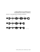
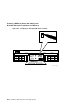
a. The DSSI ID switches behind the door of the operator control panel (OCP)
of every SF7x enclosure installed are set according to Table D–3 and
Figure D–8.
b. The MSCP switch (right-most switch of each switch pack) should be in the
down or enabled position at all times unless you are instructed to change it
to the up or disabled position.
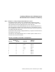
Table D–3 SF7x DSSI ID Verification (Front View)
ALL Positions
1
MSCP
Switch
Settings
Corresponding
DSSI ID Number
Left Rear (LR)
Left Front (LF)
Right Front (RF)
Right Rear (RR)
0
0
0
0
001
010
011
100
1
2
3
4
1
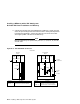
The switch settings for OCPs in these positions are 0 = down and 1 = up.
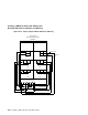
Figure D–10 shows the locations of the position numbers in the DECarray.
These numbers are in the upper right hand corner labeled 1 through 8. These
numbers are located on the front and rear DECarray cabinet uprights.
Ensure that the DSSI ID numbers of each TF857 magazine tape ISE installed
in the DECarray are set to 0 and that the TMSCP switch is enabled (down).
Refer to the TF857 magazine tape ISE documentation for the procedure to
access the DSSI adapter module.
Installing a DECarray with a VAX 4000 System D–19