
Installation guide

DECarray Cabling Information
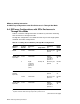
A.4 DECarray Configurations with SF3x Enclosures in Through–Bus Mode
A.4 DECarray Configurations with SF3x Enclosures in
Through–Bus Mode
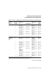
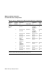
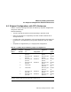
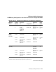
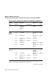
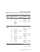
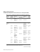
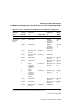
Table A–4 contains cabling information for DECarray variations containing
SF3x enclosures in through-bus mode.
Through-bus configurations are cabled the same way for both single-system
and DSSI VAXcluster configurations.
Table A–4 Cabling SF3x in DECarray Through-Bus Configurations
DECarray
Variant
Position
Number
Left DSSI
Connector
to:
1
Using Cable:
Right DSSI
Connector
to:
2
Using
Cable:
BA/BD 1 rear Terminator DECarray I/O
port P9
BC21R–
5L
BA/BD (with
tape ISEs)
1 rear Terminator Bottom
connector
of TF8x in
position 5
BC21Q–
3F
5 Right
connector
of SF3x in
position 1
(rear)
BC21Q–3F DECarray I/O
port P9
BC21R–
5L
CA/CD
(without
tape ISE)
1 rear Terminator DECarray I/O
port P9
BC21R–
5L
1 front Terminator DECarray I/O
port P10
BC21R–
5L
CA/CD (with
tape ISE)
1 rear Terminator Bottom
connector
of TF8x in
position 5
BC21Q–
3F
1
Bottom DSSI connector when referring to tape ISE in position 5 or 6.
2
Top DSSI connector when referring to tape ISE in position 5 or 6.
(continued on next page)
A–22 DECarray Cabling Information