
Installation guide

DECarray Cabling Information
A.3 Stripeset Configurations with SF7x Enclosures
A.3 Stripeset Configurations with SF7x Enclosures
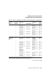
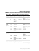
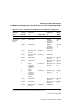
Table A–3 contains cabling information for DECarray stripeset configurations
using SF7x enclosures.
Note the following:
• The SF7x storage enclosures must be operating in split-bus mode.
• DSSI bus termination is supplied by the TTM module inside the SF7x
storage enclosures.
• If a DSSI bus is not connected to a SF7x storage enclosure, then DSSI bus
termination is accomplished by using a DSSI terminator (PN 12–31281–
01).
• Stripesets are supported only in a single-system configuration.
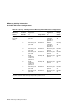
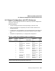
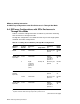
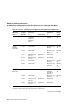
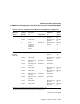
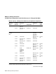
Table A–3 Cabling SF7x in DECarray Stripeset Configurations
DECarray
Variant
Position
Number
Left DSSI
Connector
to:
1
Using Cable:
Right DSSI
Connector
to:
2
Using
Cable:
All variants 1 DECarray I/O
port P2
BC21R–5L DECarray I/O
port P1
BC21R–
5L
2 DECarray I/O
port P4
BC21R–5L DECarray I/O
port P3
BC21R–
5L
3 DECarray I/O
port P6
BC21R–5L DECarray I/O
port P5
BC21R–
5L
4 DECarray I/O
port P8
BC21R–5L DECarray I/O
port P7
BC21R–
5L
5 Terminator DECarray I/O
port P16
BC21R–
5L
6 Terminator DECarray I/O
port P15
BC21R–
5L
7 DECarray I/O
port P10
BC21R–5L DECarray I/O
port P9
BC21R–
5L
8 DECarray I/O
port P12
BC21R–5L DECarray I/O
port P11
BC21R–
5L
1
Bottom DSSI connector when referring to tape ISE in position 5 or 6.
2
Top DSSI connector when referring to tape ISE in position 5 or 6.
DECarray Cabling Information A–21