
Installation guide

DECarray Cabling Information
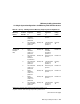
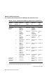
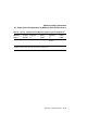
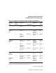
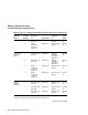
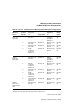
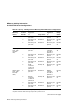
A.2 DSSI VAXcluster Configurations
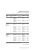
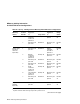
Table A–2 (Cont.) Cabling SF7x in DECarray DSSI VAXcluster Configurations
DECarray
Variant
Position
Number
Left DSSI
Connector
to:
1
Using Cable:
Right DSSI
Connector
to:
2
Using
Cable:
HE/HH
(with one
tape ISE)
1 DECarray I/O
port P9
BC21R–5L Bottom
connector
of TF8x in
position 5
BC21Q–
3F
2 DECarray I/O
port P10
BC21R–5L DECarray I/O
port P2
BC21R–
5L
3 DECarray I/O
port P11
BC21R–5L DECarray I/O
port P3
BC21R–
5L
5 Right
connector
of SF7x in
position 1
BC21Q–3F DECarray I/O
port P1
BC21R–
5L
HH/HH
(with two
tape ISEs)
1 DECarray I/O
port P9
BC21R–5L Bottom
connector
of TF8x in
position 5
BC21Q–
3F
2 Bottom
connector
of TF8x in
position 6
BC21Q–3F DECarray I/O
port P10
BC21R–
5L
3 DECarray I/O
port P11
BC21R–5L DECarray I/O
port P3
BC21R–
5L
5 Right
connector
of SF7x in
position 1
BC21Q–3F DECarray I/O
port P1
BC21R–
5L
6 Left connector
of SF7x in
position 2
BC21Q–3F DECarray I/O
port P2
BC21R–
5L
HE/HH
(plus SF7x,
without tape
ISE)
1 DECarray I/O
port P9
BC21R–5L DECarray I/O
port P1
BC21R–
5L
1
Bottom DSSI connector when referring to tape ISE in position 5 or 6.
2
Top DSSI connector when referring to tape ISE in position 5 or 6.
(continued on next page)
DECarray Cabling Information A–15