
Installation guide

Installing the SF3x Storage Enclosure in a DECarray Cabinet
5.8 DSSI Subsystem Final Verification
5.8 DSSI Subsystem Final Verification
Once the hardware installation, cabling and labeling, and the powering up
steps are complete, you are ready to configure the DSSI subsystem and check
the correct operation of each ISE in the DECarray with the host system.
Refer to the KFMSA Module Installation and User Manual and the TF857
Magazine Tape ISE Service Manual for detailed information on the correct
operation of each ISE. These manuals contain procedures for establishing
the communications between the ISEs, the adapter module, and the system.
They also contain step-by-step procedures for reconfiguring the system with its
newly installed DSSI devices.
Refer to the manuals for the disk ISE and tape ISE for detailed information on
the local programs in the ISEs.
If at any time you detect a failure, exit refer to Chapter 9.
Once the verification is complete, close the cabinet doors; turn the hex-Allen
fasteners one quarter turn clockwise to lock. The system is ready to be turned
over to the system manager.
5.9 Installing a SF36-xx Storage Enclosure in a SF2xx
Cabinet
Note
The installation of these devices is identical to the installation of SF3x
devices with the exception of the slide mounts and chassis retainers
used. Preinstalled universal slide mounts and unique lockdown
brackets are required to install SF36-xx storage enclosures.
1. Follow the hardware installation instructions in Section 5.4.2, step 1, to
install the ac power cord in the SF2xx cabinet.
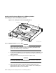
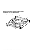
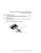
2. Using the hardware shown in (Figure 5–22), install both lockdown brackets
on the front right side (for odd number mounting positions) or front left
side (for even number mounting positions) of the enclosure extrusion tube.
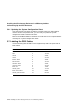
Use Table 5–5 to determine the correct lockdown bracket part number for
each installation position.
5–42 Installing the SF3x Storage Enclosure in a DECarray Cabinet