
Installation guide

Installing the SF72 Storage Enclosure in an SF200 Storage Array 5–3
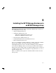
5.1 Steps to Install
The following procedures assume that the existing SF200 storage array is
correctly installed and configured.
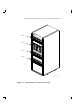
The SF72 storage enclosure that you are installing may contain two
or four RF72 disk ISEs. To determine if the SF72 contains two or four,
simply look at the front of the enclosure. Open the front door of the SF200
storage array. If you can see two disk ISEs in the front of the SF72, then
the enclosure contains four ISEs (SF72–JK variant). If you do not see
two ISEs in the front of the enclosure, then that enclosure contains only
two ISEs (SF72–HK variant). If you wish to verify an enclosure that is
already installed in a cabinet or array, observe the number of 7-segment
displays that are lit on the operator control panel (OCP). If the top two
displays are lit, then the enclosure contains only two RF72 disk ISEs.
This section contains several major parts. The first part explains the
steps to:
• Unpack, inspect for damage, and identify parts
• Determine where to install the SF72 enclosures
• Read and fill out the system configuration sheet
The next part explains the steps to install the SF72 enclosure itself:
• Prepare the array cabinet to receive an SF72 storage enclosure
• Install the supporting hardware and SF72, and set the DSSI ID
switches
• Cable the SF72 storage enclosure to comply with the DSSI bus cabling
conventions