
Installation guide

4–28 Installing an SF200 Storage Array with a VAX 6000 Series System
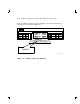
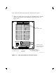
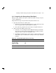
5. Observe the OCP indicators (Figure 4–14).
a. Check that the TERM PWR indicator (behind the door of the OCP)
is on for all positions installed.
b. Check that the SPLIT indicator (behind the door of the OCP) is on
for positions 3 and 8 only. Refer to Chapter 1 for an explanation
of split- and through-bus modes.
6. Press the Ready button on the OCP (Figure 4–14). The Ready
indicator flickers, then lights steadily green once the ISE is on-line.
Write
Protect
Ready Fault
DSSI
ID
Write
Protect
Ready Fault
DSSI
ID
d
i g i
t
a l
SHR_X1128_89
1
2
Figure 4–14 OCP Indicators and Controls