
Installation guide


Installing an SF200 Storage Array with a VAX 6000 Series System 4–15
4.3.2 Cabling the Storage Array (Single-Host)
Start at the rear of the SF200 storage array cabinet.
1. Plug the main power cable of the storage array into its power
receptacle.
WARNING
Hazardous voltages are in the storage array and in the
components of the storage array.
When performing any operation involving the power source,
turn off the power controls of all components and on the 881
power controller. Disconnect the power cable from the source
outlet. Perform the operation, then reconnect the power cable
to the source.
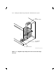
2. Connect the 108-inch DSSI cable or cables (part number BC21Q–09)
from the array DSSI I/O panel to the system I/O panel.
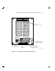
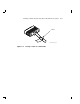
a. At the system I/O panel, remove the terminator or terminators
(part number 12–31281–01). See Figure 4–6. Store these
terminators in the ESD pouch on the rear door of the storage
array cabinet.
b. To determine which of the two DSSI connectors on the system I/O
panel to connect to:
1. Open the system I/O panel by removing the six screws that
secure it to the system chassis. Let the panel swing down to
its rest position.
2. Find the first KFMSA module installed in the system XMI
backplane. It is the KFMSA module in the lowest numbered
slot of the KFMSA modules installed.
3. Follow the cabling from the backplane to the system I/O panel.
4. While viewing the front of the I/O panel, note that the DSSI
connector on the right is KFMSA DSSI bus 1 and on the left is
bus 2.
5. For port 1 and 3 on the SF200 I/O panel, connect the 108-inch
DSSI cable to the right DSSI connector of the system I/O
panel.
6. For port 2 and 4 on the SF200 I/O panel, connect the 108-
inch DSSI cable to the left DSSI connector of the system I/O
panel.