
Installation guide


B–8 Installation Procedures for an SF72-UK Upgrade Kit
c. Verify that the disk ISE is locked into place and tighten the
wedges.
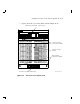
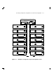
d. Connect the cables (Figure B–3) in the following order: 6-pin
power cable, 10-pin OCP cable, and 50-pin DSSI cable. The
connectors are keyed so that the cables cannot be installed
incorrectly.
NOTE TO
ILLUSTRATOR:
front panel for this
hardware is SHR_X1127_89
ISOL and reduced
17/64 (.265625)
Write
Protect
Fault
DSSI
ID
Write
Protect
Ready
Fault
DSSI
ID
d
i
g
i
t
a
l
Ready
SHR-X0135A-90
10-PIN
OCP CABLE
6-PIN DRIVE
POWER CABLE
DSSI CABLE
Figure B–3 Cabling the RF72 Disk ISE