
Installation guide


SF200 Storage Array Cabling Diagrams A–3
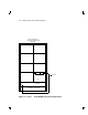
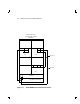
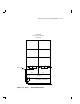
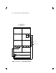
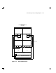
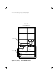
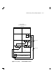
A.1 Single-Host Configuration
This section contains cabling diagrams for SF200 storage array variations
in the single-host configuration.
Note the following:
• DSSI bus termination is supplied by the TTM module inside the SF72
storage enclosures in position 3 and 8.
• The SF72 storage enclosures in positions 3 and 8 must be operating in
split-bus mode.
• If a DSSI bus is not connected to a SF72 storage enclosure in position
3 or 8, then DSSI bus termination is accomplished by using a DSSI
terminator (part number 12–31281–01).
• Split-bus mode is supported only in the single-host configuration.