
Installation guide


A
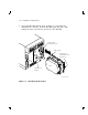
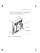
SF200 Storage Array Cabling Diagrams
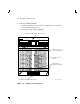
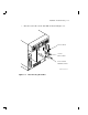
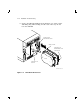
This appendix contains cabling diagrams for the SF200 storage
array variations, in both the single-host (Section A.1) and dual-host
(Section A.2) configurations.
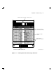
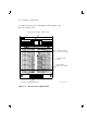
Table A–1 explains the nomenclature used in the cabling diagrams.
Table A–1 Cabling Diagram Key
T and B
R and L
Represent the top and bottom, right and left DSSI connectors
in the rear of the magazine tape subsystems and SF72 storage
enclosures.
TFx
1
SFx
2
TF is the designation for a magazine tape subsystem.
SF is the designation for a SF72 storage enclosure.
The x refers to the number of that unit.
Px Refers to the port number on the DSSI I/O panel.
Cables Three DSSI cables are used:
BC21Q–3F = 42-inch (unit to unit)
BC21R–5L = 70-inch (SF200 I/O panel to unit)
BC21Q–09 = 108-inch (SF200 to system)
T T at a DSSI connector stands for a DSSI terminator
(12–31281–01).
1
There are only two magazine tape subsystems per SF200 storage array.
2
There are up to six SF72 storage enclosures per SF200 storage array.
A–1