
Installation guide


Installation Troubleshooting 7–13
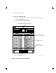
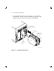
6. Verify that the disk ISE is locked into place and tighten the wedges.
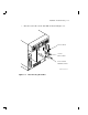
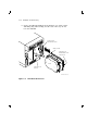
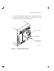
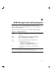
7. Connect all cables as shown in Figure 7–7. Connectors are keyed so
that the cables cannot be installed incorrectly.
NOTE TO
ILLUSTRATOR:
front panel for this
hardware is SHR_X1127_89
ISOL and reduced
17/64 (.265625)
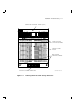
Write
Protect
Fault
DSSI
ID
Write
Protect
Ready
Fault
DSSI
ID
d
i
g
i
t
a
l
Ready
SHR-X0135A-90
10-PIN
OCP CABLE
6-PIN DRIVE
POWER CABLE
DSSI CABLE
Figure 7–7 Cabling the RF72 Disk ISE