
Installation guide


Installing the Magazine Tape Subsystem in an SF200 Storage Array 6–27
6.2.1.1 Cabling Position 5
WARNING
Before performing the following steps, refer to the system
documentation for the correct steps to perform an orderly
shutdown of the system that the SF200 storage array is connected
to.
The following steps are for cabling a magazine tape subsystem in an
existing SF200 storage array configured for single-host:
1. Take the disk ISEs in position 1 off-line before you proceed. To do
so, first take each ISE off-line by pressing the Ready switches. Then
press all the drive dc power switches to the out position. Last, turn
off the ac power at the rear of the storage enclosure.
CAUTION
Use care not to disturb or damage power cords and DSSI
cables that are already connected to the DSSI I/O panel.
2. Disconnect the 70-inch DSSI cable (part number BC21Q–3F)
connected to the rightmost DSSI connector at the rear of the SF72
enclosure in position 1.
3. Pull the inner assembly to the head-cleaning position (first mechanical
stop).
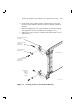
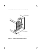
4. Connect the 70-inch DSSI cable removed from position 1 (Figure 6–11)
and connect it to the top DSSI connector on the rear of the magazine
tape subsystem. Route this DSSI cable under the cable retainers on
the right side of the cabinet.
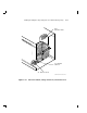
5. Connect a 42-inch DSSI cable (part number BC21Q–3F) to the
rightmost DSSI connector at the rear of the SF72 in position 1
and to the bottom DSSI connector at the rear of the magazine tape
subsystem in position 5. Route this DSSI cable under the cable
retainers on the right side of the cabinet.
6. Push the inner assembly back into the extrusion tube.
CAUTION
Do not power up the magazine tape subsystem or the SF72 storage
enclosure at this time.