
Installation guide

1–6 Introduction
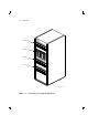
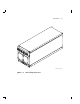
The SF72 storage enclosure has the following features:
• The SF72 storage enclosure can operate in one of two modes: through-
bus or split-bus.
– When in through-bus mode, all of the disk ISEs connect to a
single common DSSI bus inside the SF72 enclosure. The DSSI
bus is terminated by connecting to one of the following: a DSSI
terminator (part number 12–31281–01), another SF72 storage
enclosure operating in the split-bus mode (while in single-
host configuration), or another host system (while in dual-host
configuration).
Host configurations are explained later in this guide. Refer to the
KFMSA Module Installation and User Manual (EK–KFMSA–IM)
for a more detailed explanation.
– When in split-bus mode, the disk ISEs on the left side of the
enclosure connect to a different DSSI bus than the disk ISEs on
the right side. Also, both DSSI buses terminate inside the SF72
on the transition termination module (TTM) behind the OCP. By
connecting one SF72 enclosure (operating in through-bus mode)
to an SF72 storage enclosure (operating in split-bus mode), two
DSSI buses with six disk ISEs each are obtained. This mode of
operation is used in single-host configurations only.
• Each RF72 disk ISE has its own set of switches and indicators on the
OCP.
• The enclosure power supply provides operating power to the
subassemblies of the enclosure. The rear panel of the power supply
contains the ac power switch for the SF72.
• Two DSSI connectors are at the top rear of the enclosure. The DSSI
bus runs to each disk ISE in the enclosure.
• The drive dc power switches for the disk ISEs are on the front panel
of the SF72 enclosure. Each switch contains a symbol to indicate its
associated disk ISE and an LED that lights when power is applied to
that disk ISE.
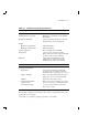
Specifications for the SF72 storage enclosure are shown in Table 1–2.