
Installation guide


5–74 Installing the SF72 Storage Enclosure in an SF200 Storage Array
5.3.1 Updating the System Configuration Sheet
Now that the enclosure has been successfully installed, power has been
applied, and the drives have passed POST, you are ready to update the
system configuration sheet to add the new ISEs.
Refer to the KFMSA Module Installation and User Manual (EK–KFMSA–
IM) for complete details on how to fill out a system configuration sheet.
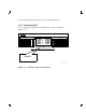
5.4 Labeling the DSSI Cables and OCP
For a single-host configuration, use the following colored labels on the
SF72 OCP door, magazine tape subsystem front panel, and all DSSI
cables:
Label Colors Connections
Blue Port 1, positions 5, 1, 3
Red Port 2, positions 6, 2, 3
Yellow Port 3, positions 4, 8
Green Port 4, positions 7, 8
For a dual-host configuration, use the following colored labels on the SF72
OCP door, magazine tape subsystem front panel, and all DSSI cables:
Label Colors Connections
Blue Port 1, positions 5 and 1, port 9
Red Port 2, positions 6 and 2, port 10
Yellow Port 3, position 3, port 11
Green Port 4, position 4, port 12
Blue with white strip Port 5, position 7, port 13
Red with white strip Port 6, position 8, port 14
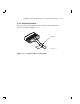
5.4.1 Filling Out the Labels
Follow the steps on the inside of the SF Family Label Booklet (part
number 36-32882-01) to fill out the labels for the DSSI cables and SF72
operator control panels.
Proceed once you have filled the cable and OCP labels.