
Installation guide


Installing the SF72 Storage Enclosure in an SF200 Storage Array 5–53
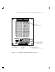
6. Follow the cabling from the backplane to the system I/O panel.
7. While viewing the front of the I/O panel, note that the DSSI connector
on the left is KFMSA DSSI bus 2 and the DSSI connector on the right
is KFMSA DSSI bus 1. These connectors should be labeled YELLOW
for bus 1 and GREEN for bus 2.
8. Find the next KFMSA module installed in the XMI backplane of each
system. It will be the next KFMSA module after the KFMSA module
in the previous steps.
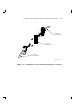
9. Follow the cabling from the backplane to the system I/O panel.
10. While viewing the front of the I/O panel, note that the DSSI connector
on the left is KFMSA DSSI bus 2 and the DSSI connector on the
right is KFMSA DSSI bus 1. These connectors should be labeled
BLUE/WHITE for bus 1 and RED/WHITE for bus 2.
If these connectors are not labeled, label them now with the small colored
labels in the SF Family Label Booklet (part number 36–32882–01).