
Installation guide


5–52 Installing the SF72 Storage Enclosure in an SF200 Storage Array
5.2.2 Dual-Host Configuration
Use the following procedures for cabling an SF72 storage enclosure in an
existing SF200 storage array configured for dual-host.
The following procedures assume that all devices installed previous to an
new installation of an SF72 storage enclosure are cabled in the dual-host
configuration.
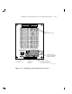
5.2.2.1 Identifying DSSI Connectors on the System I/O Panel
The following procedure explains how to locate and identify the DSSI
connections on the VAX 6000 system I/O panel.
WARNING
Before performing the following steps, refer to the system
documentation for the correct steps to perform an orderly
shutdown of the systems that the storage array is connected
to.
NOTE
This procedure assumes that no SF72 storage enclosures are
installed internally in the system cabinet. If there are SF72
storage enclosures installed in the system cabinet, then one of
the KFMSA modules installed in the system XMI backplane must
be connected to those SF72 storage enclosures. DO NOT USE this
KFMSA module or its DSSI connections to connect the system to
the SF200 storage array. DO NOT COUNT this KFMSA module in
the following steps.
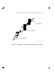
1. Open the system I/O panels on both systems by removing the six
screws that secure the I/O panel to the system chassis. Let the panel
swing down to its rest position.
2. Find the first KFMSA module installed in the XMI backplane of each
system. It will be the KFMSA module in the lowest numbered slot of
the XMI backplane.
3. Follow the cabling from the backplane to the system I/O panel.
4. While viewing the front of the I/O panel, note that the DSSI connector
on the left is KFMSA DSSI bus 2 and the DSSI connector on the right
is KFMSA DSSI bus 1. These connectors should be labeled BLUE for
bus 1 and RED for bus 2.
5. Find the next KFMSA module installed in the XMI backplane of each
system. It will be the next KFMSA module after the KFMSA module
in the lowest numbered slot of the XMI backplane.