
Installation guide


5–50 Installing the SF72 Storage Enclosure in an SF200 Storage Array
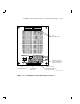
5.2.1.5 Cabling Position 3 or 8
WARNING
Before performing the following steps, perform an orderly
shutdown of the system that the SF200 storage array is connected
to.
The following steps describe cabling for positions 3 and 8. Note that
positions 3 and 8 operate in split-bus mode for a single-host configuration.
1. Power down the SF72 storage enclosures in position 1 and 2 if you are
installing in position 3. Power down the SF72 storage enclosures in
position 4 and 7 if you are installing in position 8. To power down an
enclosure, first press the Ready button for each ISE, then press each
drive dc power switch (one at a time), and finally at the rear of the
enclosure press the ac power switch to 0.
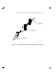
2. Install a 42-inch DSSI cable (part number BC21Q–3F) (Figure 5–23)
to the rightmost DSSI connector on the rear of the SF72 storage
enclosure in position 3 or 8.
3. Route this DSSI cable under the cable retainers on the right side of
the cabinet for position 3. For position 8, route this cable above the
SF72 storage enclosures in positions 7 and 8.
4. For position 3, connect this 42-inch DSSI cable to the leftmost DSSI
connector at the rear of the SF72 in position 1. For position 8, connect
this 42-inch DSSI cable to the leftmost DSSI connector at the rear of
the SF72 in position 7.
5. Install a 42-inch DSSI cable (part number BC21Q–3F) (Figure 5–23)
to the leftmost DSSI connector on the rear of the SF72 in position 3 or
8.
6. Route this DSSI cable under the cable retainers on the right side
of the cabinet for position 3 and on the left side of the cabinet for
position 8.
7. For position 3, connect this 42-inch DSSI cable to the leftmost DSSI
connector at the rear of the SF72 in position 2. For position 8, connect
this 42-inch DSSI cable to the leftmost DSSI connector at the rear of
the SF72 in position 4.
WARNING
Do not apply power to the SF72 storage enclosure at this time.