
Installation guide

Installing the SF72 Storage Enclosure in an SF200 Storage Array 5–47
5.2.1.4 Cabling Position 4 or 7
WARNING
Before performing the following steps, refer to the system
documentation for the correct steps to perform an orderly
shutdown of the system that the SF200 storage array is connected
to.
The following steps are for cabling positions 4 and 7:
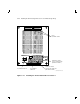
1. At the rear of the SF200 storage array, locate the DSSI I/O panel at
the bottom. Use a 3/16-inch flatblade screwdriver to loosen the two
captive screws at the right of the panel.
2. Swing open and remove the panel from the cabinet frame.
CAUTION
Use care not to disturb or damage power cords and DSSI
cables that are already connected to the DSSI I/O panel.
3. Remove the two Phillips screws that hold the panel blank in port 3
(for position 4) or port 4 (for position 7).
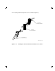
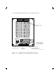
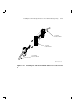
4. Install a 70-inch DSSI cable (part number BC21R–5L) in place of the
panel blanks you just removed in the previous step. Secure this cable
to the I/O panel with the two Phillips screws removed from the blank
panel (Figure 5–22).
5. Plug the other end of the 70-inch DSSI cable into the rightmost DSSI
connector at the rear of the SF72 storage enclosure, in either position
4 or 7.
6. Route this DSSI cable under the cable retainers on the appropriate
side of the cabinet, left side for position 4, and right side for position
7.
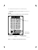
7. Plug a 108-inch DSSI cable (part number BC21Q–09) into the port
you just installed in the previous steps (Figure 5–22). Tighten the
retainer screws on the 108-inch DSSI cable with your fingers.