
Installation guide

Installing the SF72 Storage Enclosure in an SF200 Storage Array 5–45
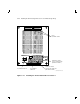
The following steps are for cabling position 2 with a magazine tape
subsystem in position 6:
CAUTION
Use care not to disturb or damage power cords and DSSI
cables that are already connected to the DSSI I/O panel.
1. Tighten the shipping screw in the rear, upper right corner, of the
magazine tape subsystem in position 6.
2. Remove the DSSI terminator from the bottom DSSI connector on the
rear of the magazine tape subsystem in position 6.
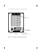
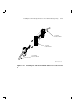
3. Install a 42-inch DSSI cable (part number BC21Q–3F) in the bottom
DSSI connector on the rear of the magazine tape subsystem in
position 6 (Figure 5–20).
4. Loosen the shipping screw in the rear, upper right corner, of the
magazine tape subsystem in position 6.
5. Pull the inner assembly of the magazine tape subsystem out to the
head-cleaning position (first mechanical stop).
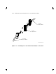
6. Route this DSSI cable under the cable retainers on the left side of
the cabinet. Cabling the magazine tape subsystem with the inner
assembly pulled out to the head-cleaning position ensures that the
correct cable slack will be provided when the inner assembly is
pushed back into the extrusion tube.
7. Push the inner assembly of the magazine tape subsystem back into
the extrusion tube.
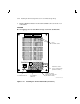
8. Connect the 42-inch DSSI cable from the bottom DSSI connector on
the rear of the magazine tape subsystem in position 6 to the rightmost
DSSI connector on the rear of the SF72 storage enclosure in position
2.
NOTE
Perform the next step if this is the only SF72 storage enclosure
to be installed on this particular DSSI bus. If not, then
proceed to the cabling instructions for the next SF72 storage
enclosure that has been installed.