
Installation guide

1
Introduction
This chapter provides an overview of the SF200 storage array and the
SF72 storage enclosure, with specifications. A related documents list
provides references to supplemental information.
1.1 SF200 Storage Array Overview
The SF200 storage array is a storage rack cabinet designed to hold SF72
storage enclosures and magazine tape subsystems.
The SF200 storage array is intended to be installed on one or both sides
of a host system. All operator control panels (OCPs) project through the
front door of the storage array to allow easy access. The DSSI (Digital
Storage System Interconnect) cables from the host cabinet input/output
(I/O) panel connect to the DSSI I/O panel at the bottom rear of the storage
array. The DSSI I/O panel supports as many as 16 individual DSSI buses.
A fully configured single-host SF200 storage array uses four DSSI buses.
A fully configured dual-host SF200 storage array uses six DSSI buses.
The remaining unused DSSI buses are for future use.
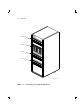
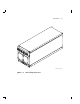
Viewing the SF200 storage array from the front, note that the SF72
storage enclosures and magazine tape subsystems are arranged in the
storage array as follows (Figure 1–1):
• Levels 1, 2, and 4 are reserved for SF72 storage enclosures only.
SF72 storage enclosure upgrades are installed into these levels in the
following order: position 1, 2, 3, 4, 7, and 8.
• Level 3 is reserved for magazine tape subsystems. Magazine tape
subsystem upgrades are installed into this level in the following order:
position 5 then 6.
NOTE
The position numbers are visible on the right and left chassis side
rails when the front and rear doors of the storage array are open.
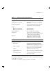
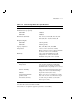
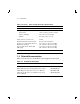
Specifications for the SF200 storage array are shown in Table 1–1.
1–1