
Installation guide

Installing the SF72 Storage Enclosure in an SF200 Storage Array 5–11
5.1.4 Installation Procedure
Before attempting any of the following steps, ensure that the SF72
enclosures installed in the array cabinet contain four disk ISEs.
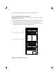
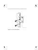
To determine if the SF72 contains two or four drives, simply look at the
front of the enclosure. If you can see two drives in the front of the SF72,
then the enclosure contains four drives (SF72–JK variant). If you do not
see two drives in the front of the enclosure, then that enclosure contains
only two drives (SF72–HK variant). If you wish to verify an enclosure
that is already installed and running in a cabinet or array cabinet,
observe the number of 7-segment displays that are lit on the operator
control panel (OCP). If the top two displays are lit, then the enclosure
contains only two RF72 disk ISEs.
The procedure for installing the upgrade kit is in Appendix B.
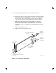
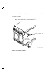
This section describes the step-by-step procedures for installing an SF72
storage enclosure in SF200 storage array positions 1, 2, 3, 4, 7, or 8.
Be sure to:
• Follow each step in order, and do not skip any steps
• Leave sufficient room to perform the installation (approximately 1.5
meters to 1.8 meters [5 feet to 6 feet] front and rear of the array)
CAUTION
Observe all ESD precautions and procedures.
An antistatic wrist strap is inside the front and rear doors.
CAUTION
Do not attempt to pick up or support the SF72 by the handle
in the rear of the enclosure. Doing so will injure the person
attempting the installation or damage the power supply.
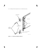
To maintain stability, only one SF72 storage enclosure or
magazine tape subsystem should be extended on the slide mounts
at a time.