
Technical data


Linkage with PLC
CP 486 ⋅ 00/14 VIPA GmbH 103
6. Linkage with PLC
6.1 General Description
Data transfer between CP486 and PLC is supported by handling modules on PLC side and by
software interrupts on CP side. Following routines are available:
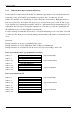
Operation on PLC side Operation on CP side
Bank 0 PLC job: read data from CP
(PLC active)
Handling module
(FB3)
Interrupt service routine
Bank 1 PLC job: send data to CP
(PLC active)
Handling module
(FB3)
Interrupt service routine
Bank 2 CP job: read data from PLC
(CP486 active)
Cyclically called han-
dling module (FB1)
Software interrupt
Bank 3 CP job: send data to PLC
(CP486 active)
Cyclically called han-
dling module (FB1)
Software interrupt
Bank 4 reserved
Bank 5 reserved
Bank 6 reserved for standard CP
operation
(Send, Receive, Control, ..)
Bank 7 Transfer process image to CP Cyclically called han-
dling module (FB1)
Software interrupt or direct
access to bank
Following data structures in the PLC can be accessed on CP side:
- single elements in format byte, words and doublewords
DB, DX, markers, inputs, outputs, timer, counter, flag word
- data blocks
DB, DX, FB, FX, OB, PB, SB, BA, BB, BT, BS
Following PLC accesses to CP are possible:
the linkage supports all types of MS-DOS device-oriented accesses.
all jobs issued by the PLC are based on MS-DOS device functions.
Functions described below are available upward for CP386COM version 1.00 (Software CP4-
SW593 version 2.00) and handling module version 2.00 (CP4-SW977 and CP4-SW978 version
2.00). The program CP386COM is named in the following description as COM-driver.